6.6 Transfer Procedure (Using a Modem)
6-53
6
Transfer with V8
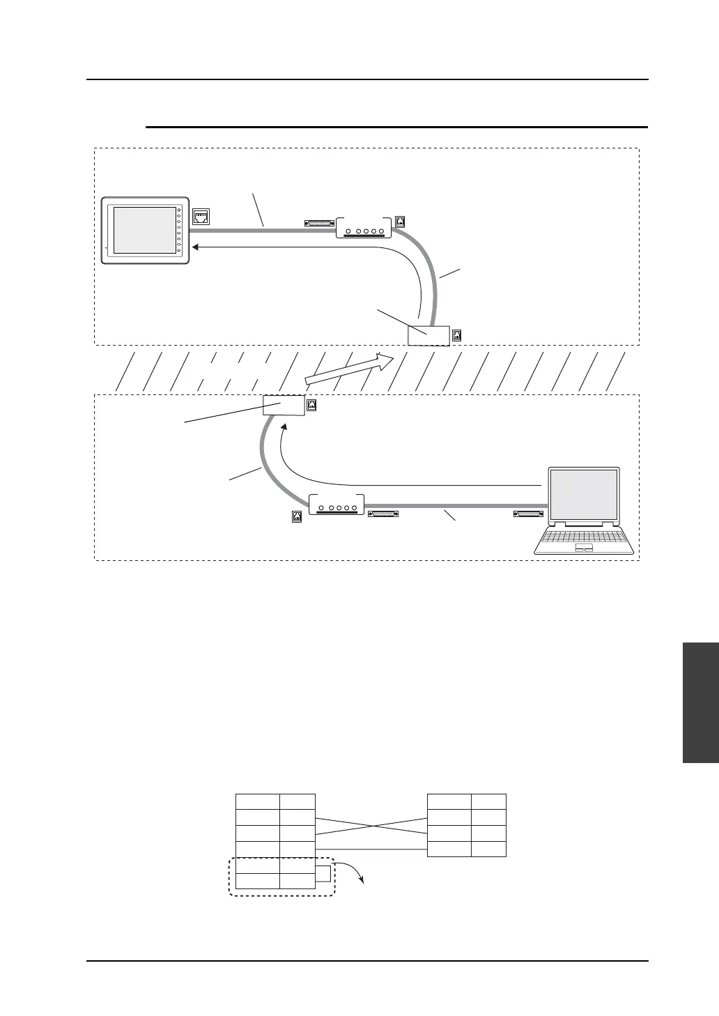
Description of Connections
Connection between V series and modem (A)
• Connect V-CP to the MJ1 on the back of the V series.
• Connect the RS-232C cable accompanying the modem to the RS-232C connector on the back of
the modem.
• The cable to connect V-CP and the RS-232C cable accompanying the modem should be arranged
for by the customer.
• Cross cable connection diagram
The V-CP is a cross cable. To bring the signal connection to a straight state, manufacture another
cross cable to be connected.
MJ1
PW ER OH CD DA
LINE
PW ER OH CD DA
LINE
F 1
F 2
F 3
F 4
F 5
F 6
F 7
SYSTEM
RS-232C cable
included with the
modem (straight)
Computer
(PC)
Telephone line
RS-232C cable (straight)
(V-CP + cross cable + RS-232C cable included with the modem)
Modular cable included
with the modem
Modular cable included
with the modem
Telephone line
modular socket
Telephone line
modular socket
Modem
Modem
Receive side
Send side
A
B
C
B
RD
SD
SG
2
3
5
RTS
CTS
7
8
RD
SD
SG
2
3
5
9-pin connector of the modem
* For a modem that is not capable of flow control
setting, install a jumper between RTS and CTS.
Modem (9-pin) V-CP (9-pin) male
Signal Name
Pin No.
Signal Name
Pin No.