Parts Editing
A3-5
A3
Parts Editing
Switch / Lamp
Structure
Procedure
This section explains the procedure for editing a switch part. The same procedure applies to lamp part
editing.
1. Select the switch part you wish to edit, and open the [Modify Part] window.
2. Using drawing icons, etc., edit its design as desired.
For editing procedure with drawing icons, refer to “4 Drawing” page 4-1.
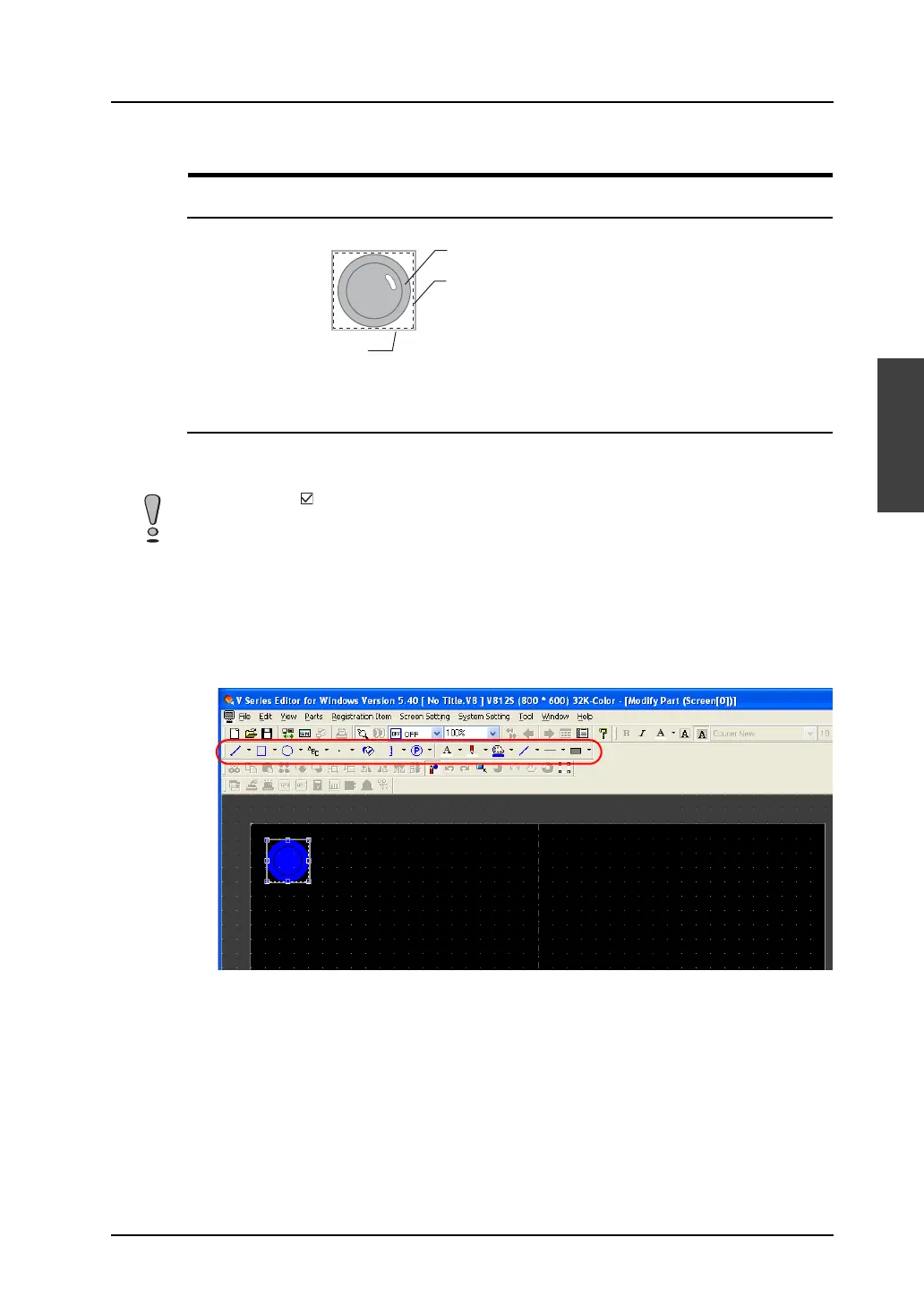
Frame (part area)
Graphic data
Part basic area (= touch area*)
* The touch area exists for switch parts only.
In a case where [ Place switches on switch grids.] ([View] → [Grid]) is checked, placing or scaling a
switch part or setting its touch area is based on the switch grid.
With a V8 unit of the analog switch type, unchecking the above option allows you to edit a switch on a
dot-by-dot basis, independently from the switch grid. With a V8 unit of the matrix switch type, however,
be sure to check [Place switches on switch grids.] before editing a switch part.