Parts Editing
A3-6
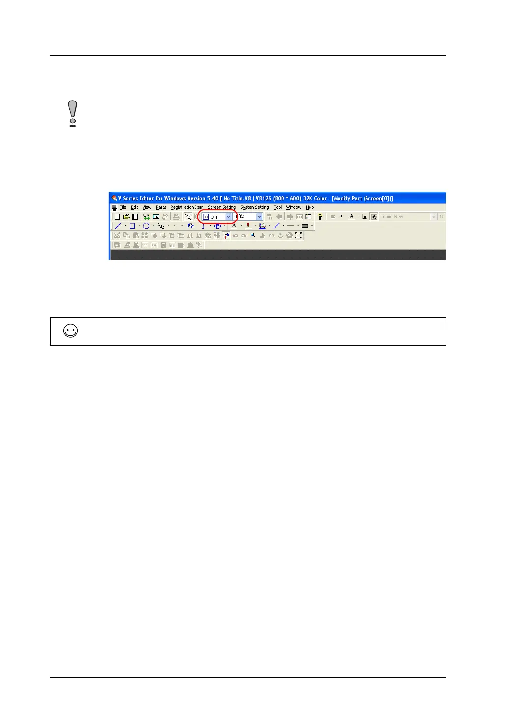
3. When you proceed to editing the other patterns of the switch, select a pattern from [OFF], [ON],
[P3], and after, and follow step 2.
* For more information on graphic properties, refer to “Properties of graphic frames and
areas” (page A3-7).
4. On completion of editing the patterns of the switch, set its touch area again.
For more information on setting the touch area, refer to “Re-setting the touch area” (page A3-7).
5. Set the frame of the switch part again.
For how to re-set the frame, refer to “Re-setting the frame” (page A3-9).
6. Go back to the base screen.
• For creating a switch or a lamp, the graphic of its ON pattern is placed over the graphic of its OFF
pattern. Even a slight deviation from each other will not display the switch or the lamp correctly. In
the [Modify Part] window, copy the graphic of the OFF pattern. Change the window to the window
for ON pattern editing and paste the copy to the window.
• Whether the patterns (OFF, ON, P3 and after) of a switch or a lamp you edited are displayed on
MONITOUCH as intended depends on the [Draw Mode: XOR or REP] in the [Style] tab window of
the item dialog. Extra care is needed in this mode setting.
A lamp part, which has no touch area, needs re-setting its basic area instead.
For how to re-set the area, refer to “Re-setting the part basic area” (page A3-8).