Parts Editing
A3-9
A3
Parts Editing
Re-setting the frame
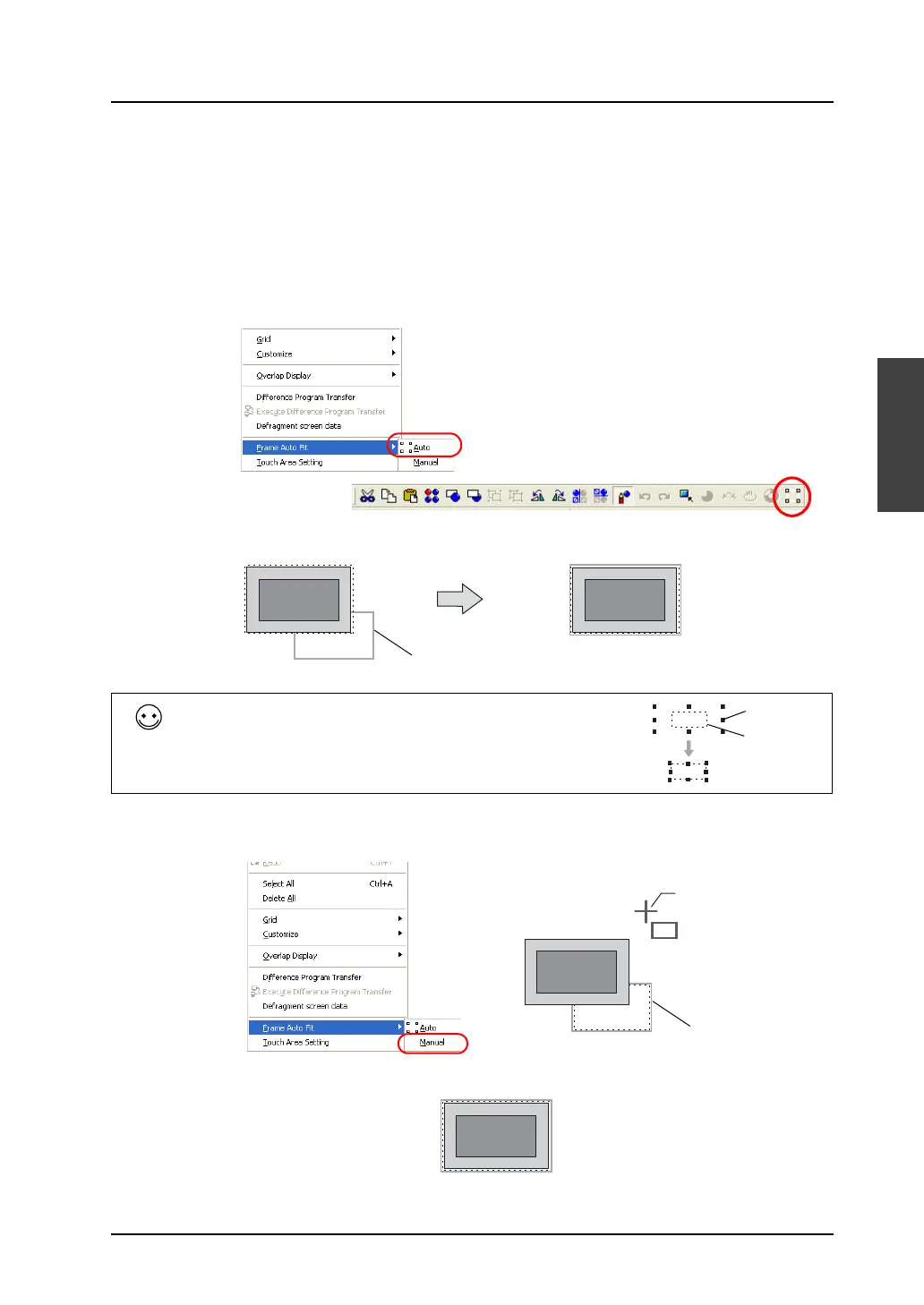
Every part has a frame (in default color: gray). The frame of a part denotes its overall size, comprising
the graphic data and the basic area (the touch area in the case of a switch part). For a graphic freely
drawn, its frame may not fit the size of the drawn graphic. Re-setting the frame is required to avoid
such a deviation problem.
There are the following two methods of frame setting:
• Automatic setting
1) In the right-click menu, click [Frame Auto Fit] → [Auto], or click the [Frame Auto Fit] icon on the
toolbar.
2) The frame is fit to the graphic data and the touch area.
• Manual setting
1) In the right-click menu, click [Frame Auto Fit] → [Manual]. A cross-shaped cursor appears.
2) Adjust the frame to the desired position by dragging the cross-shaped cursor.
OR
A frame is fit to the shape
of the part.
Frame
Frame re-setting is also executable on the base screen.
Select the target part (or parts), and follow the either procedure:
• In the right-click menu, click [Change Part] → [Frame Auto Fit].
• Click [Edit] → [Change Part]→ [Frame Auto Fit].
1234
1234
Frame
Part basic
area
Cross-shaped cursor
Frame