Parts Editing
A3-19
A3
Parts Editing
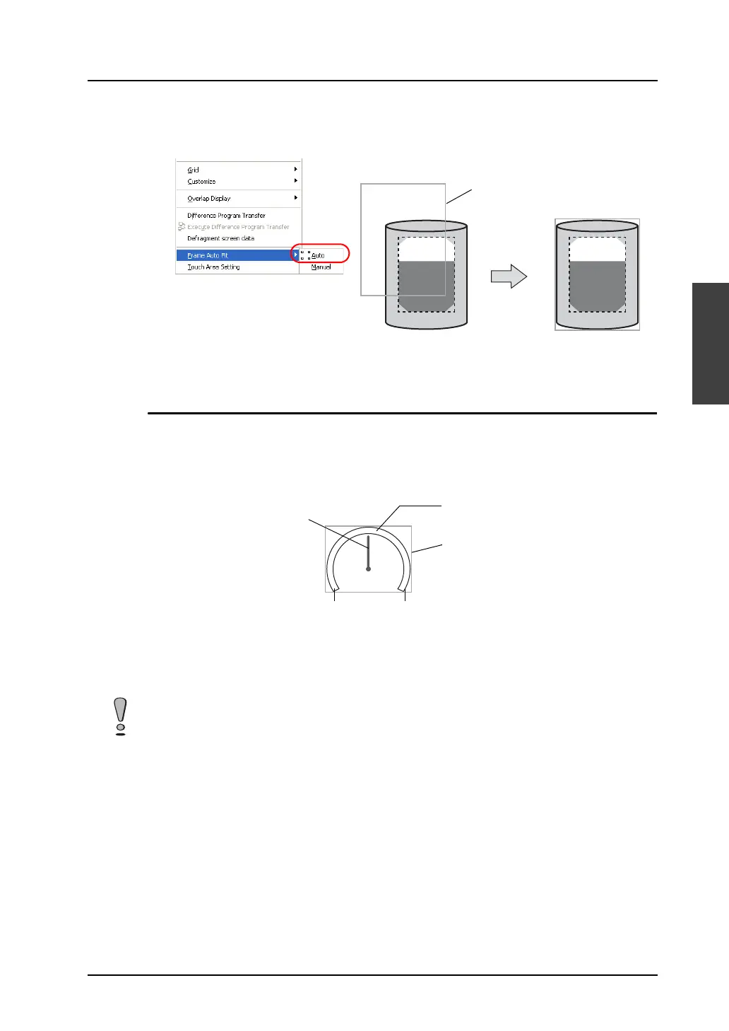
5. On completion of editing, click [Frame Auto Fit] in the right-click menu.
For more information on the frame and its setting method, refer to “Re-setting the frame” (page
A3-9).
6. Go back to the base screen.
Panel Meter
Structure
A panel meter part is almost the same as a pie graph part in structure. When a pie graph part is
adopted as the part basic area, the panel meter shows a graph value with the area painted in [Target
Value] color. Meanwhile, a panel meter with an indicator shows a graph value with the indicator.
Procedure
The editing procedure is the same as that for pie graph parts.
For more information, refer to “Pie Graph” (page A3-13).
Frame
Part basic area
Indicator
Start angle End angle
Frame (part area)
Every panel meter part contains an internal circle. When editing a panel meter part, the [With Internal
Circle] icon is inactive. Minimum permissible sizes are designated for panel meter parts. The
minimum radius of the internal circle is set to 10 dots, and the minimum difference between the radii of
the internal circle and the external circle is set to 16 dots.