Parts Editing
A3-23
A3
Parts Editing
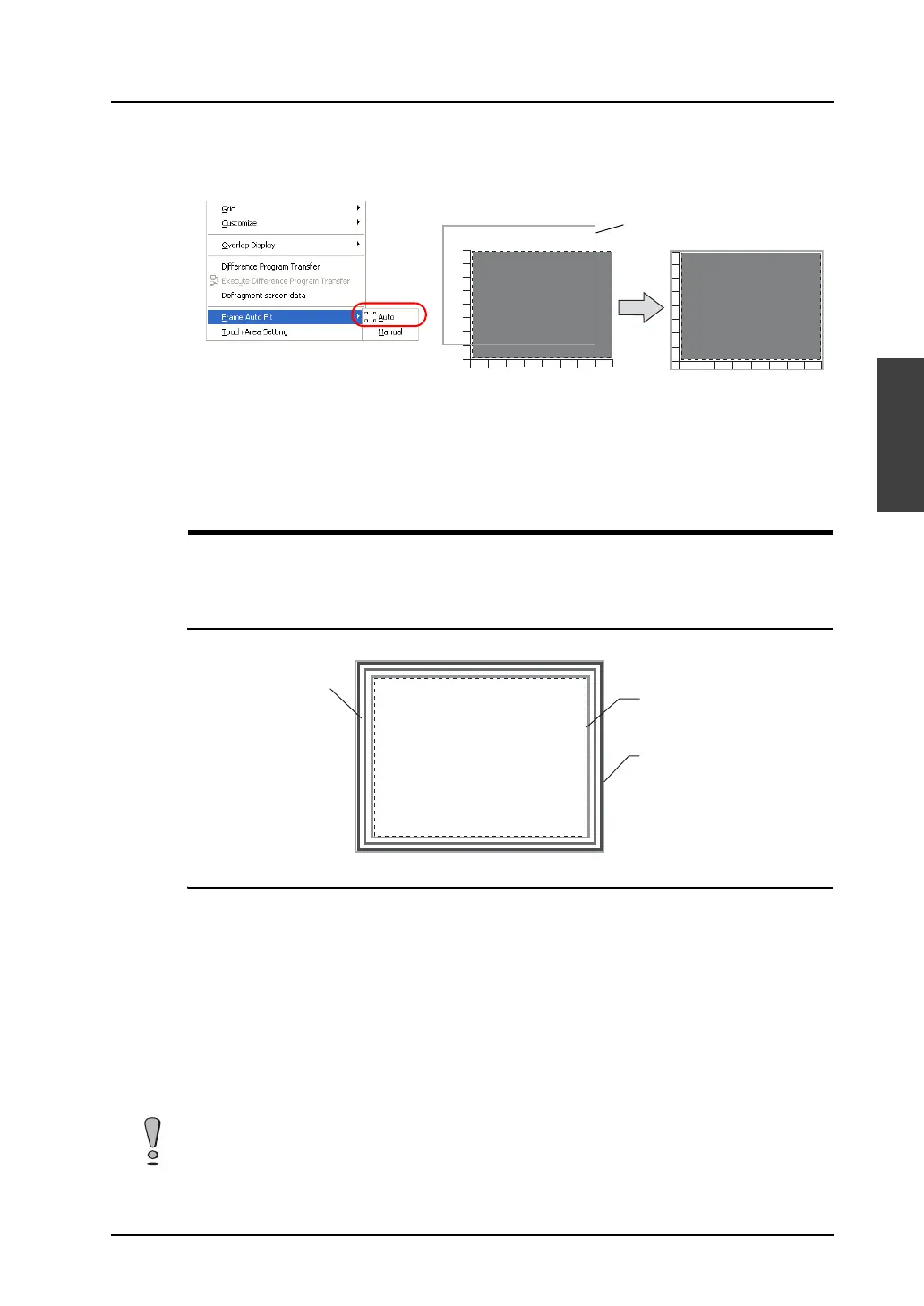
3. On completion of editing, click [Frame Auto Fit] in the right-click menu.
For more information on the frame and its setting method, refer to “Re-setting the frame” (page
A3-9).
4. Go back to the base screen.
Display Area
Display area parts are used to display messages for bit order alarming or in the message mode, or to
display graphics in the graphic mode.
Structure
Procedure
The editing procedure is almost the same as that for overlap editing.
For more information on editing, refer to “Overlap” (page A3-4).
However, frame setting is allowed for display area parts. Unlike an overlap display part, the basic area
and the graphic area of a display area part are independent from each other. In the course of editing a
display area part, frame re-setting is necessary to determine the size of the part.
For more information on the frame, refer to “Re-setting the frame” (page A3-9).
* The components of a display area part are linked. Therefore, the components need to be
unlinked prior to editing. In the right-click menu, click [Link] → [Link Cancel]. Or, click
[Edit] → [Link] → [Link Cancel].
Once the components are unlinked, linking them again is recommended after editing is
finished.
Draw scales placed
along the graph part.
The frame is fit to the
graph part including the
scales.
Frame
Part basic area
Graphic data
Frame (part area)
Note that graphics drawn in the part basic area will not be displayed correctly on MONITOUCH.