8.7 Other Functions in the [Tool] Menu
8-70
5. Choose [Bit] or [Word]. Memory change is performed in units of bits or words as selected.
6. Enter the first address of the memory addresses to be changed for [Before Change Start Memory]
Likewise, enter the last address of the memory addresses to be changed for [Before Change End
Memory].
7. Enter the desired first address after change for [After Change Start Memory] in the same manner.
8. When settings are completed, click [OK]. The former [Batch Change Memory] dialog is displayed
again.
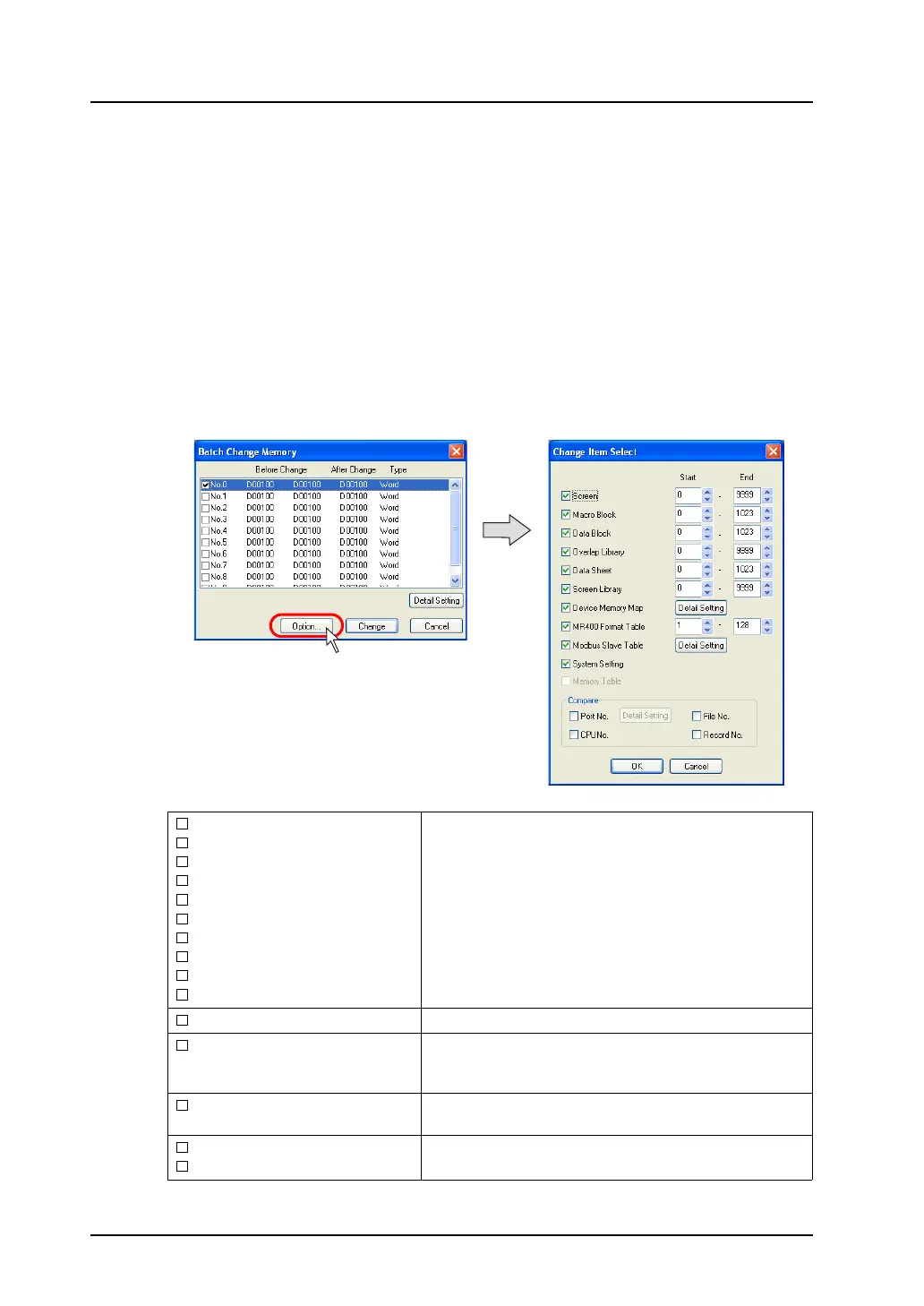
9. Click [Option] and select items of which memory addresses should be changed.
For more information, refer to the next section.
10. Click [Change]. The specified memory addresses are changed in a batch.
Option setting
Clicking the [Option] button in the [Batch Memory Change] dialog brings up the following [Change Item
Select] dialog.
Screen
Macro Block
Data Block
Overlap Library
Data Sheet
Screen Library
Device Memory Map
MR400 Format Table
Modbus Slave Table
System Setting
Check the options targeted for memory change.
For specifying the range of memory addresses, enter the
desired numbers for [Start] and [End].
Memory Table
This option is used for component parts.
Port No.
This option is valid when [1:n] (multi-drop) is selected for
[Connection Mode]. Check this option to include the port
numbers of PLC1 - PLC8 in targets for memory change.
CPU No.
Check this option when a CPU number is set for the
connected device.
File No.
Record No.
Check these options to include memory card addresses in
targets for memory change.