8.1 Simulator
8-9
8
Useful Functions
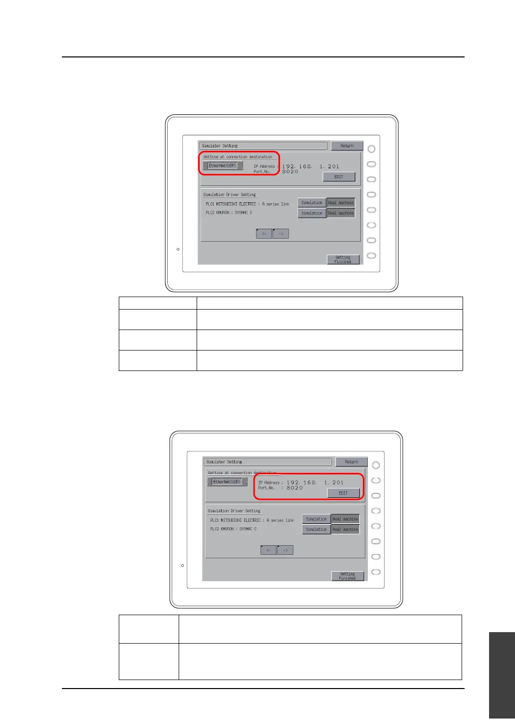
2. The Simulator Setting screen is displayed.
Check that what is displayed under [Setting at connection destination] coincides with the actual
communication format between MONITOUCH and the computer.
3. When [EtherNet (UDP)] is selected for [Setting at connection destination], proceed to setting the
[IP Address] and [Port No.].
When [MJ1 (Serial)] or [USB-B (Device)] is selected for [Setting at connection destination], go to
step 4.
Display Remarks
MJ1 (Serial) Simulator is run while connection is established between MJ1 (modular jack 1) of
MONITOUCH and the computer with the V-CP cable.
EtherNet (UDP) Simulator is run while connection is established between the LAN port of
MONITOUCH and the computer with the LAN cable.
USB-B (Device) Simulator is run while connection is established between the USB-B port of
MONITOUCH and the USB-A port of the computer with the USB cable.
IP Address Specify the IP address of the target computer.
Pressing the [EDIT] switch calls up the keypad. Key in the IP address on the keypad.
The default IP address is “192.168.1.201”.
Port No. Specify the port number for Simulator. Pressing the [EDIT] switch calls up the keypad.
Key in the port number on the keypad.
This port number must be the same as the port number in the [Communication Setting]
dialog for Simulator ([File] → [Communication Setting]). The default is “8020”.
F 1
F 2
F 3
F 4
F 5
F 6
F 7
SYSTEM
F 1
F 2
F 3
F 4
F 5
F 6
F 7
SYSTEM