3.2 Setting Up Editing Environment
3-5
3
Screen Editing
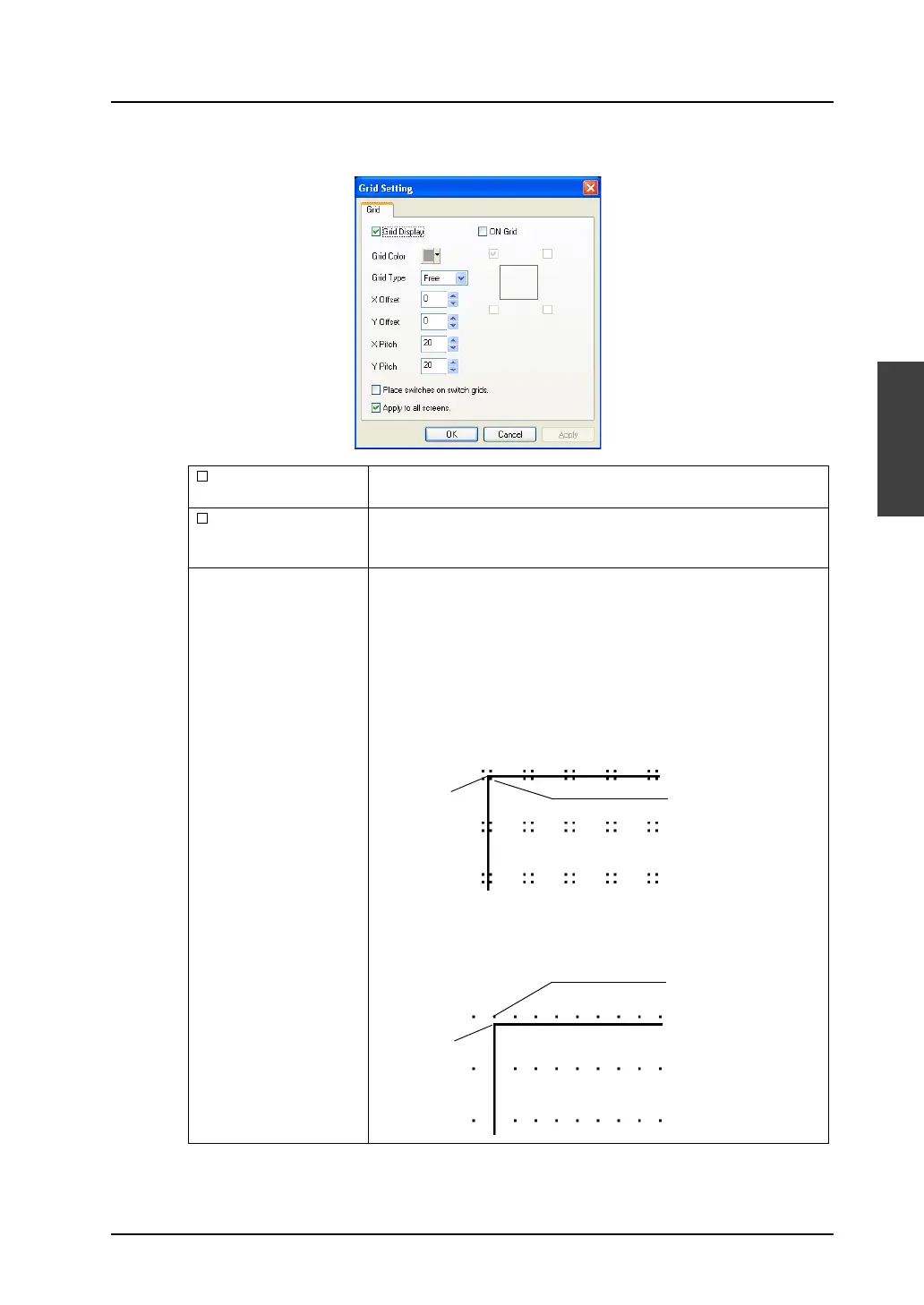
[Grid Setting] dialog
Grid Display Shows grids when this option is checked.
Unchecking this option clears grids from the screen.
ON Grid When this option is checked, items are moved or changed based on
the grid.
(“ON Grid” is not valid for overlap displays.)
Grid Type
(Free / Switch / 1-Byte /
Mode)
Allows you to select the grid type.
Free:
You can freely set a desired grid.
Switch:
This grid is used for the matrix type switch.
The grid is based on the unit: 16 × 20 dots (the unit of switch: 14 × 18
dots plus spaces: 2 × 2 dots). The datum point is placed at the
coordinates (1, 1).
1-Byte:
The grids are based on the unit: 8 × 20 (the unit of one-byte
character: 8 × 16 dots plus four Y-axis dots). The reference point is
placed at coordinates (0, −3).
Origin point
(0, 0)
Grid offset position
(1, 1)
Origin point
(0, 0)
Grid offset position
(0, −3)