3.2 Setting Up Editing Environment
3-6
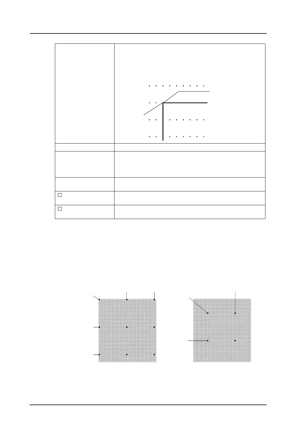
*1 Relation between “offset” and “pitch”
Grids are placed from the offset point at intervals specified by X and Y pitches as shown in the
examples below.
Mode:
The mode grid is equivalent to the one-byte character grids, but its
offset position differs.
The mode grid is based on the unit: 8 × 20 dots. The datum point is
placed at the origin point (0, 0).
Lines and columns are used to indicate item positions.
Grid Color Allows you to select the desired grid color.
X Offset *1
Y Offset
This option is active when [Free] is chosen for [Grid Type].
The offset coordinate is specified.
* The offset coordinate can be specified for [Grid Offset Position]
selected from the [Grid] right-click menu.
X Pitch *1
Y Pitch
This option is active when [Free] is chosen for [Grid Type].
The pitch is specified.
Place switches on
switch grids.
When this option is checked, switches are moved or changed based
on the switch grid, irrespective of the grid setting.
Apply to all screens. When this option is checked, the grid settings are applied to all screen
editing windows.
Origin point
(0, 0)
Grid offset position
(0, 0)
(20, 0)
(0, 20)
(0, 40)
(0, 0)
(40, 0)
(30, 10)
(10, 30)
(10, 10)
Offset point Offset point
Ex. 1)
[X Offset: 0]
[Y Offset: 0]
[X Pitch: 20]
[Y Pitch: 20]
Ex. 2)
[X Offset: 10]
[Y Offset: 10]
[X Pitch: 20]
[Y Pitch: 20]