MAX32665-MAX32668 User Guide
Maxim Integrated Page 114 of 457
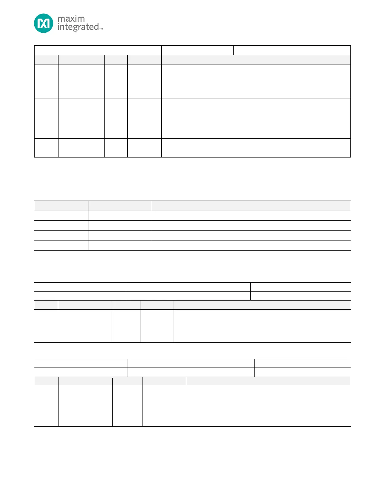
QSPI0 Function Select
0: High speed 96MHz oscillator
1: External clock input
Note: See the GPIO chapter for the external clock input pin
USB Reference Clock Source Select
This selects the clock source for the USB Hi-Speed Interface.
0: High speed 96MHz oscillator
1: External clock input
See the GPIO chapter for the external clock input pin
Reserved
Do not modify this field.
4.20 AES Key Registers
See Table 3-1: APB Peripheral Base Address Map for the AES Key Registers’ Peripheral Base Address.
Table 4-78: AES Key Register Summary
128-bit AES Key Register 0
128-bit AES Key Register 1
128-bit AES Key Register 2
128-bit AES Key Register 3
4.21 AES Key Register Details
Table 4-79: AES Key 0 and 1 Registers
AES 128-bit Key Registers
These two registers make up the 256-bit AES key, with the most significant
bits in AES_KEY1 and the least significant bits in AES_KEY0.
This register is reset only on AoD Reset.
Table 4-80: AES Key 2 and 3 Registers
AES 128-bit Key Registers
Each of these registers are loaded at system initialization with user-
defined 128-bit keys.
See the secure bootloader section in the TPU supplement for
more information.