MAX32665-MAX32668 User Guide
Maxim Integrated Page 134 of 457
7. Flash Controller (FLC)
The Flash Controller manages read, write, and erase accesses to the internal flash. It provides the following features:
• Up to 1 MB total internal flash memory
• 128 pages
• 8,192 bytes per page
• 2,048 words by 128 bits per page
• 128-bit data reads and writes
• Page erase and mass erase support
• Write protection
7.1 Instances
The device provides two instances of the FLC.
The 1MB of internal flash memory is organized as two distinct instances of 512KB, each with its own dedicated controller,
for storing user application and data. These internal flash memory instances are programmable via serial wire debug
interface (in-system) or directly with user application code (in-application).
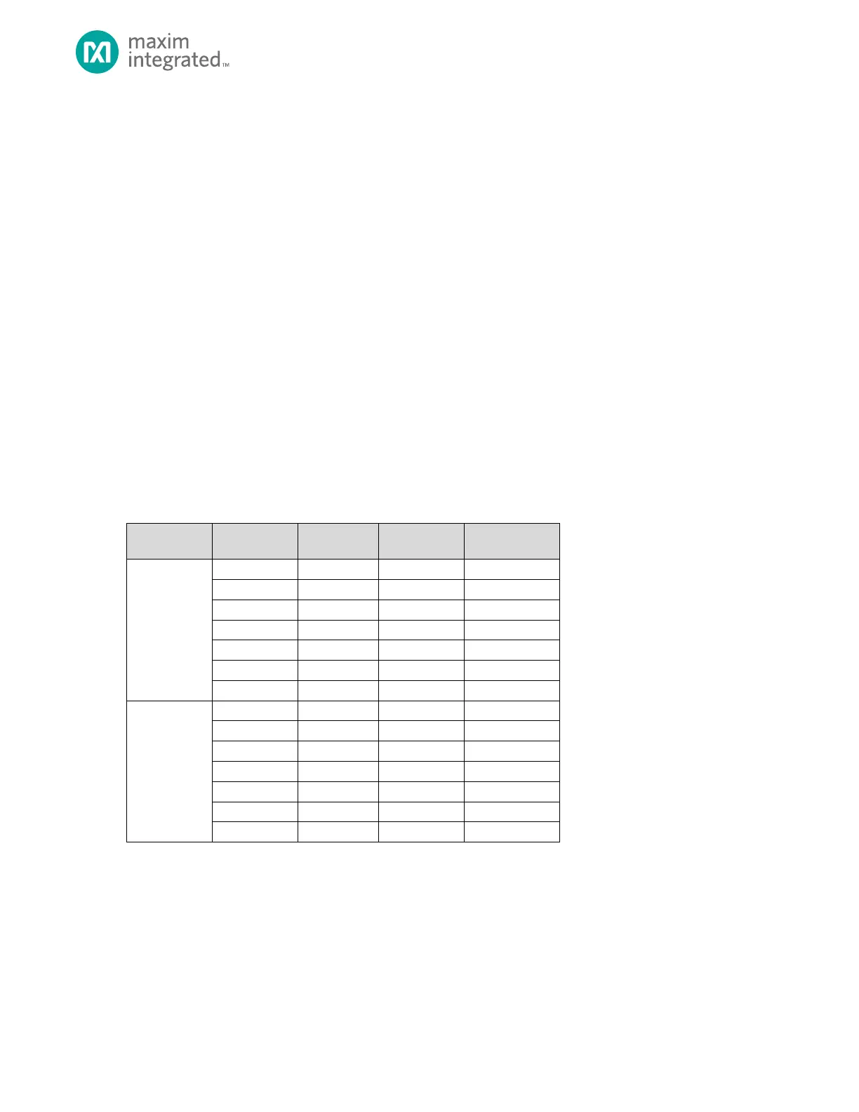
The flash instances are organized as an array of pages. Each page is 2,048 words by 128 bits, or 8,192 bytes per page. Table
7-1, below, shows the start address and end address for each flash instance. The internal flash memory is mapped with a
start address of 0x1000 0000 and an end address of 0x100F FFFF for a total of 1MB.
Table 7-1: MAX32665—MAX32668 Internal Flash Memory Organization
7.2 Usage
Each Flash Controller manages write and erase operations for internal flash memory and provides a lock mechanism to
prevent unintentional writes to the internal flash. In-application and in-system programming, page erase and mass erase
operations are supported.