MAX32665-MAX32668 User Guide
Maxim Integrated Page 327 of 457
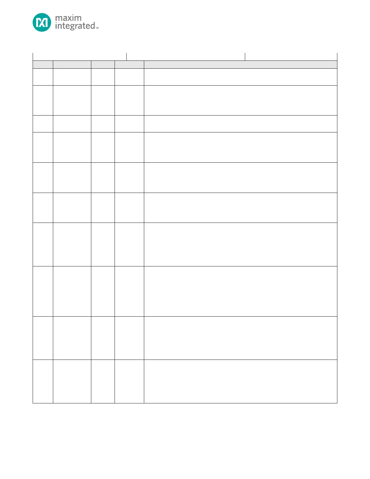
Table 15-6: HTimer Control Register
Reserved for Future Use
Do not modify this field from its default value.
Write Enable
Software must set this bit to 1 before writing to HTIMER_CTRL.enable.
1: Writes to HTIMER_CTRL.enable are allowed.
0: Writes to HTIMER_CTRL.enable are ignored.
Reserved for Future Use
Do not modify this field from its default value.
Short-Interval Alarm Interrupt Flag
This flag is a wake-up source for the processor.
0: No short-interval alarm pending.
1: Short-interval interrupt pending.
Long-Interval Alarm Interrupt Flag
This flag is a wake-up source for the processor.
0: No long-interval alarm interrupt pending.
1: Long-interval interrupt pending.
Timer Ready Interrupt Enable
This interrupt flag is set when the timer ready bit is set by hardware.
0: Interrupt disabled.
1: Interrupt enabled.
Timer Ready
This bit is set to 1 by hardware when HTIMER_SEC.rts is updated. Software can clear
this bit at any time. Hardware automatically clears this bit just prior to updating the
HTIMER_SEC.rts, indicating the timer is busy.
0: HTIMER_SEC register not updated.
1: HTIMER_SEC register updated.
Timer Busy Flag
This bit is set by hardware when changes to the registers are synchronized. The bit is
automatically cleared by hardware when the synchronization is complete. Software
should poll this field for 0 after changing registers to ensure the change is complete
prior to making any other register changes.
0: Not busy.
1: Busy.
Short-Interval Alarm Interrupt Enable
Set this bit to 1 to enable the short-interval alarm interrupt. Check the
HTIMER_CTRL.busy flag after writing this bit to determine when the register
synchronizations are complete.
0: Short-interval alarm interrupt disabled.
1: Short-interval alarm interrupt disabled.
Long-Interval Alarm Interrupt Enable
Set this bit to 1 to enable the long-interval alarm interrupt. Check the
HTIMER_CTRL.busy flag after writing to this bit to determine when the timer
synchronization is complete.
0: Long-interval alarm interrupt is disabled.
1: Long-interval alarm interrupt is enabled.