MAX32665-MAX32668 User Guide
Maxim Integrated Page 159 of 457
8.2.2.1 SPIXF Pin Configuration
The SPIXF Master and SPIXF Master Controller use a highly-configurable, flexible, and efficient interface supporting single,
dual, or quad I/O. Dedicated pins are provided to support high-speed communication. The following pin configurations are
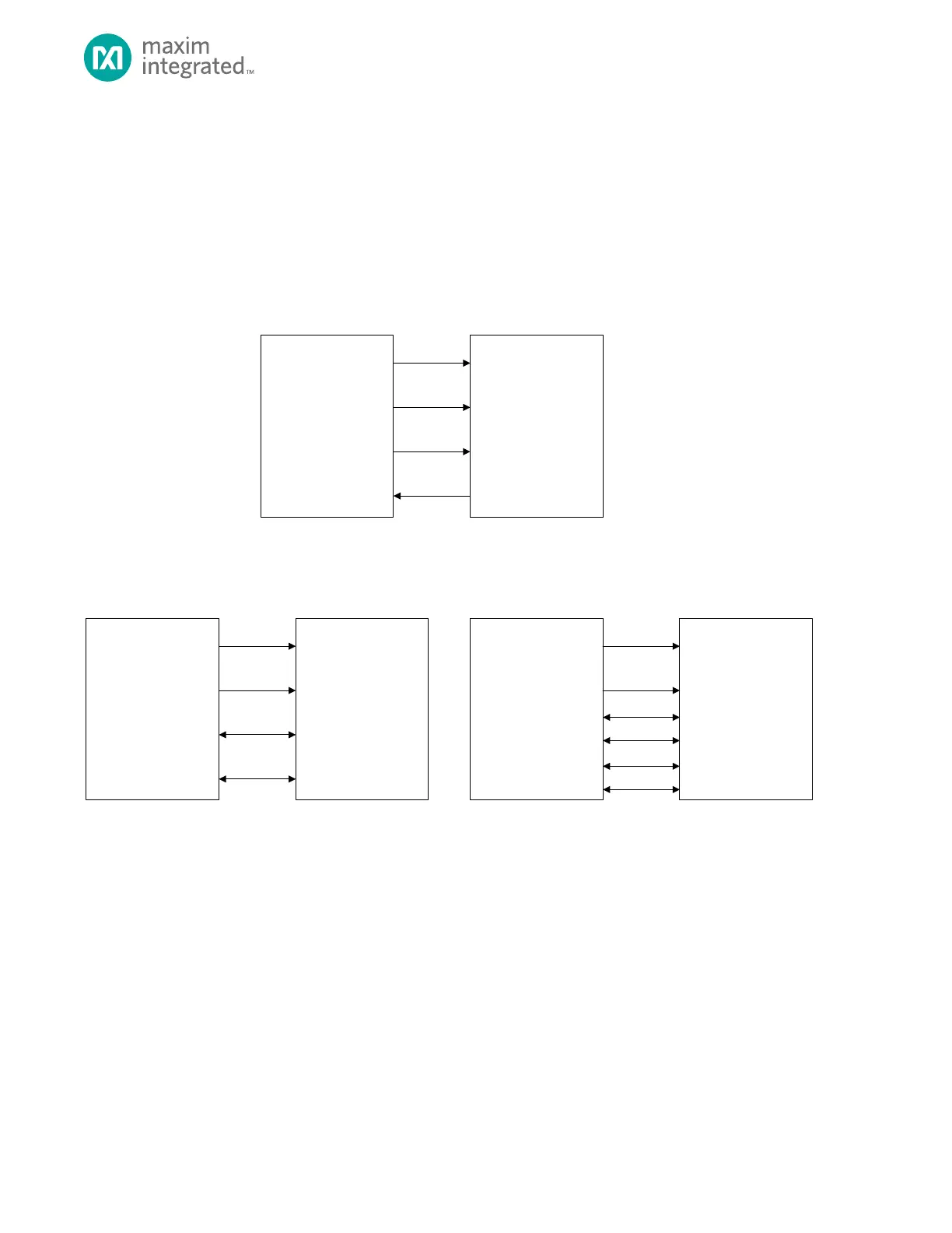
supported and shown in Figure 8-4:
• Four-wire SPI: SS, SCK, MOSI on SDIO0, and MISO on SDIO1
• Dual SPI: SS, SCK, SDIO0, and SDIO1
• Quad SPI: SS, SCK, SDIO0, SDIO1, SDIO2, and SDIO3
Figure 8-4. Supported SPI configuration
8.2.2.2 Slave-Select Transaction Delay Configuration
The transaction delay and clock timing with respect to the active or inactive slave-select edge is determined by a
combination of the following register fields:
• SPIXFM_CFG.ssact
• SPIXFM_CFG.ssinact
• SPIXFM_CFG.hiclk
• SPIXFM_CFG.loclk
• SPIXFM_CFG.mode
Automatic slave-select de-assertion only occurs when the next flash address fetched is not contiguous to the current flash
address that is being read or used for execution. The SPIXF does not automatically de-assert slave selection under any other
circumstance including data read or execution of areas outside of the SPIXF space. For these cases, manual control of the
slave select is provided. Invoke manual control only when running from internal memory. You can de-assert slave-select
safely by setting GCR_RST1.spixip. This resets the SPIXF block (including turning off decryption if previously enabled) and