MAX32665-MAX32668 User Guide
Maxim Integrated Page 403 of 457
21.2 USBHS Bus Signals
A USB cable connects a USB Host, which controls the transfer, and a USB Device, which is controlled by the Host. The USBHS
Peripheral is a USB Device. A USB cable has four conductors (three hardware signals plus ground). These signals can be
duplicated more than once in a physical USB cable. The signals in a USB cable are as follows:
• D+ (DPLUS): Positive line of the differential data pair.
• D- (DMINUS): Negative line of the differential data pair.
• VBUS: Bus voltage supplied by Host.
• Ground
When a USB Device is attached to a USB Host, the USB Host identifies the speed of the USB Device by the presence of a
pullup resistor on either D+ or D-. The Host then begins the Enumeration sequence. The Enumeration sequence allows the
Host to identify the type and characteristics of the Device attached to the Host so that it can load the proper drivers for the
Device. Enumeration always uses Endpoint 0. The Host requests and reads from the Device the contents of the USB
Endpoint Descriptor Table that tells the Host everything it needs to know about the capabilities of the USB Device. The Host
then assigns the USB Device an address, which firmware writes to the USBHS_FADDR.faddr bit field.
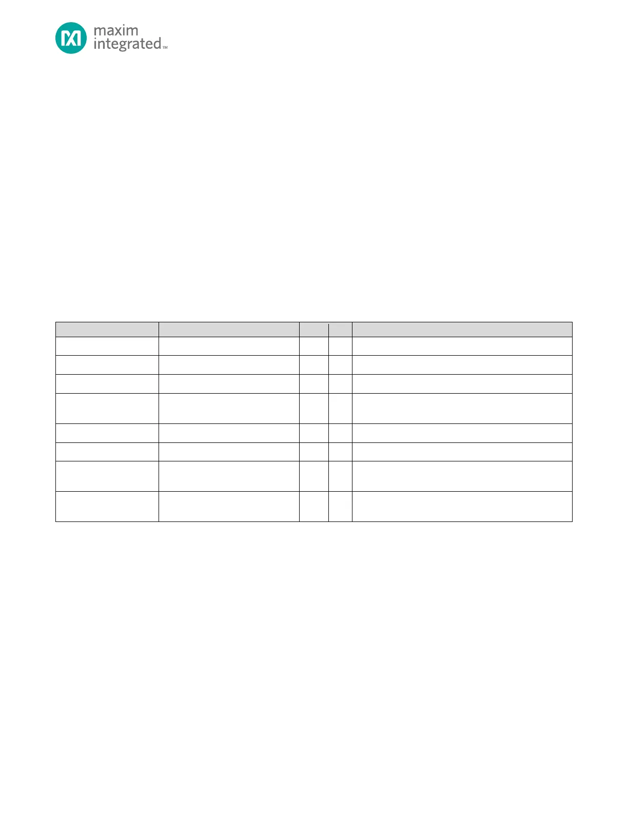
Table 21-1 shows the USB Bus states seen by the Host indicated by the differential pair.
Table 21-1: USB Bus States Indicated by the Differential Pair (D+, D-)
Host or Device is driving the bus
Host or Device is driving the bus
Illegal state. This state should never occur on a properly
configured USB bus.
No Host or Device is driving the bus
USB Device is Full Speed. No activity on bus.
No Host or Device is driving the bus
USB Device is Low Speed. No activity on bus.
Device wants to disconnect from
Host
Held for 2.5µs or longer.
Host is initiating communication
with a Device
USB communication is based on the above basic conditions, which are used to generate the following states:
• Data J State – Same as IDLE state, but bus is actively driven by either the Host or the Device.
• Data K State – Opposite of J state. Bus is actively driven by the Host or the Device.
• RESUME – Data K State. Tells Device to exit SUSPEND mode.
• START OF PACKET (SOP) – Bus switches from IDLE to K state.
• END OF PACKET (EOP) – SE0 for two bit periods, then J state for one bit period.
• KEEP ALIVE Signal – EOP sent every 1 millisecond.
21.3 USBHS Device Endpoints
Each USB Device supports one or more endpoints. Endpoints serve as a source or destination for data and are supported by
memory buffers. This USB controller supports 12 endpoints, each with its own set of descriptors and data buffers. These
Endpoints are referenced as Endpoint 0 through Endpoint 11.