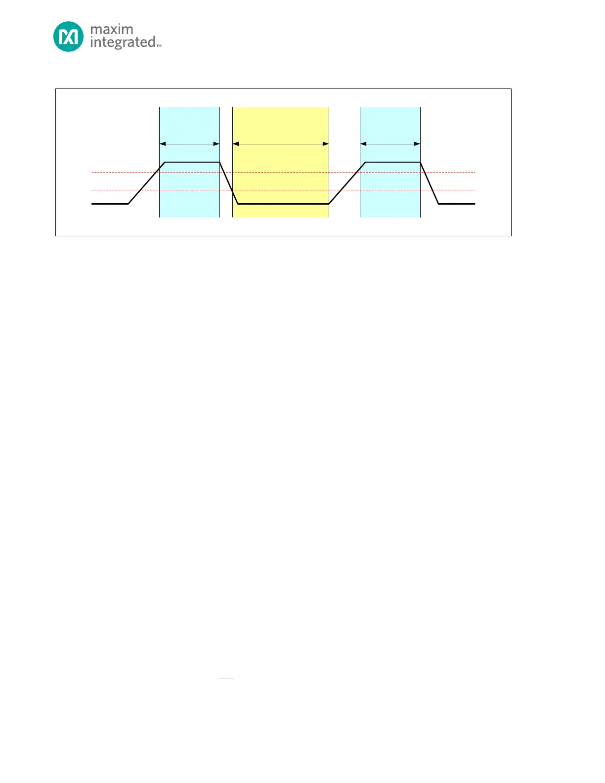
During synchronization, external masters or external slaves may be driving SCL simultaneously. This affects the SCL duty
cycle. By monitoring SCL, the controller can determine whether an external master or slave is holding SCL low. In either
case, the controller waits until SCL is high before starting to count the number of SCL high cycles. Similarly, if an external
master pulls SCL low before the controller has finished counting SCL high cycles, then the controller starts counting SCL low
cycles and releases SCL once the time period, I2Cn_CLK_LO.scl_lo, has expired.
Because the controller does not start counting the high/low time until the input buffer detects the new value, the actual
clock behavior is based on many factors. These include bus loading, other devices on the bus holding SCL low, and the filter
delay time of this device.
13.4.4 SCL Clock Generation for Hs-mode
To operate the I
2
C interface in Hs-mode at its maximum speed (~3.4MHz), values to be programmed into the I2Cn_HS_CLK
.hs_clk_lo register and I2Cn_HS_CLK.hs_clk_hi register must be determined. Since the Hs-mode operation is entered by first
using one of the lower speed modes for pre-amble, a relevant lower speed mode must also be configured. See SCL Clock
Generation for Standard, Fast and Fast-Plus Modes for information regarding configuration of lower speed modes.
13.4.4.1 Hs-Mode Timing
With I
2
C bus capacitances less than 100pf, the following specifications are extracted from the I
2
C-bus Specification User
Manual Rev. 6 April 2014 https://www.nxp.com/docs/en/user-guide/UM10204.pdf
t
LOW_MIN
, the minimum low time for the I
2
C bus clock, = 160ns
t
HIGH_MIN
, the minimum high time for the I
2
C bus clock, = 60ns
t
rCL_MAX
, the maximum rise time of the I
2
C bus clock, = 40ns
t
fCL_MAX
, the maximum fall time of the I
2
C bus clock, = 40ns
13.4.4.2 Hs-Mode Clock Configuration
The maximum Hs-mode bus clock frequency can now be determined. The system clock frequency, f
SYS_CLK
, must be known.
Hs-mode timing information from Hs-Mode Timing must be used.
Equation 13-3: I2C Target SCL Frequency
This is the desired target for the maximum I
2
C clock speed.
.