MAX32665-MAX32668 User Guide
Maxim Integrated Page 241 of 457
CRC Data Output Register 0 (Bits 63:32)
CRC Data Output Register 0 (Bits 95:64)
CRC Data Output Register 0 (Bits 127:96)
CRC Pseudo-Random Number Register
10.4 Register Details
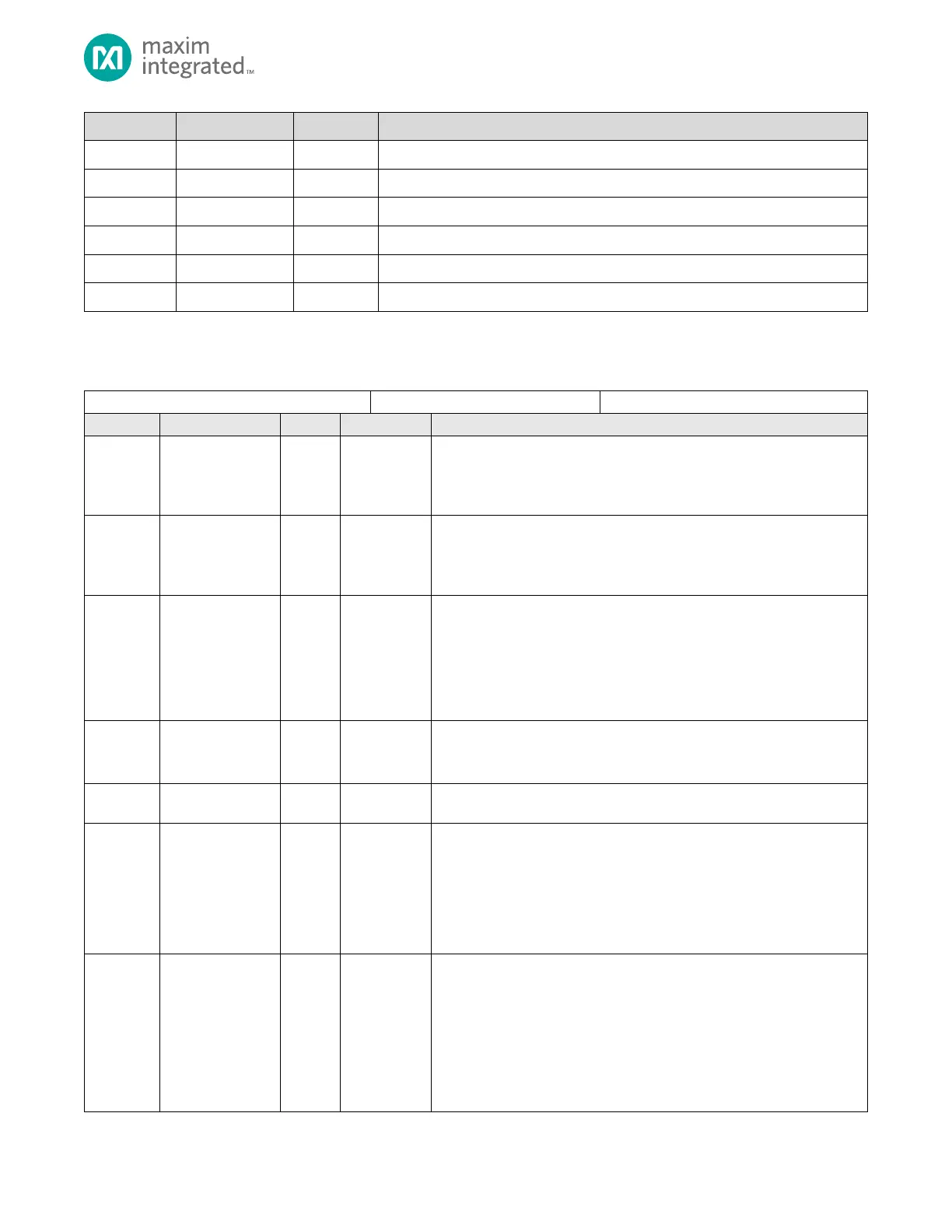
Table 10-3. Flash Controller Address Pointer Register
Done
Done bit indicator.
0: CRC not done.
1: CRC done.
Ready
CRC engine ready for operation.
0: CRC engine busy.
1: CRC engine ready for operation.
Error Flag
If this field reads 1 an error occurred.
0: No error condition.
1: Error occurred.
Reserved for Future Use
Do not modify this field.
DMA Complete Flag
This field is set to 1 when a DMA read/write operation is complete. Set this
field to 0 prior to starting a DMA CRC operation.
Reserved for Future Use
Do not modify this field.
DMA Done Flag Mask for DMA Operation
This field sets the behavior of the CRYPTO_CTRL.done flag. Setting this bit
to 1 results in a CRYPTO_CTRL.dma_done complete to set the
CRYPTO_CTRL.done field. The setting for this field does not affect the
actual behavior of the CRYPTO_CTRL.dma_done flag.
0: DMA Complete Flag is not used for setting CRYPTO_CTRL.done field.
1: DMA Complete condition sets the CRYPTO_CTRL.done field.
Done Flag Mode
This field configures the access behavior of the CRYPTO_CTRL.dma_done
bit. When this field is set to 1, the CRYPTO_CTRL.dma_done bit is Write 1
to Clear. When this field is 0, the CRYPTO_CTRL.dma_done bit is
unrestricted read/write.
0: CRYPTO_CTRL.dma_done bit is unrestricted read/write access.
1: CRYPTO_CTRL.dma_done bit is Write 1 to Clear.
Note: This field is only reset on a Power-On Reset.