MAX32665-MAX32668 User Guide
Maxim Integrated Page 308 of 457
Table 14-2: MAX32665—MAX32668 QSPI Signal Mapping shows the mapping of the QSPI alternate functions.
Table 14-2: MAX32665—MAX32668 QSPI Signal Mapping
14.2 SPI Formats
14.2.1 Four-Wire SPI
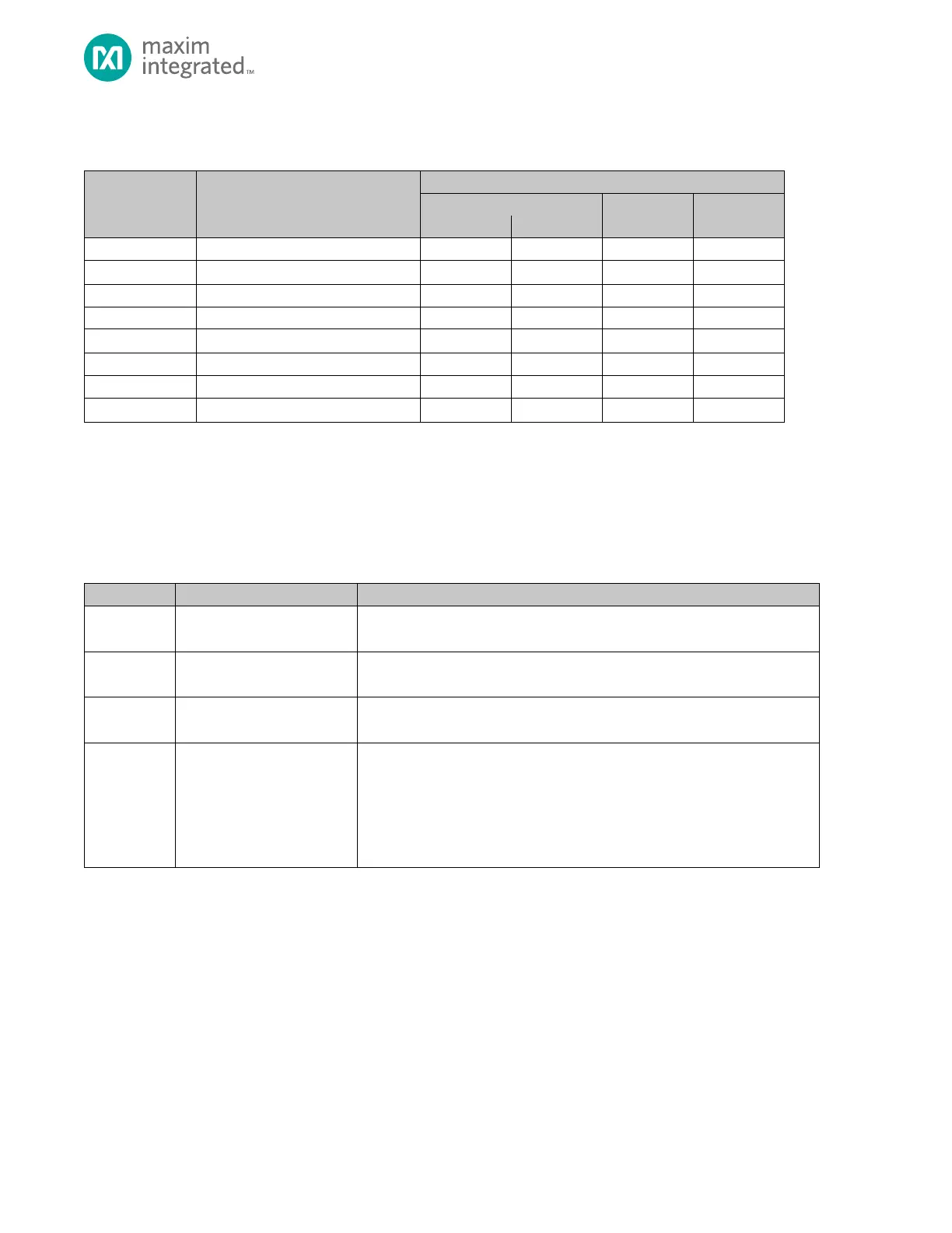
SPI devices operate as either a master or slave device. In four-wire SPI, four signals are required for communication as
shown in Table 14-3, below.
Table 14-3: Four-Wire Format Signals
The master generates the Serial Clock signal, which is an output from the
master and an input to the slave.
Master Output Slave Input
In master mode, this signal is used as an output for sending data to the slave.
In slave mode this is the input data from the master.
Master Input Slave Output
In master mode, this signal is used as an input for receiving data from the slave.
In slave mode, this signal is an output for transmitting data to the master.
In master mode, this signal is an output used to select a slave device prior to
communication. Peripherals may have multiple slave select outputs to
communicate with one or more external slve
In slave mode QSPIn_SS0 is a dedicated input which indicates an external
master is going to start communication. Other slave select signals into the
peripheral are ignored in slave mode.
The MAX32665—MAX32668 supports up to three slave select lines for each instance, QSPIn_SS0, QSPIn_SS1 and
QSPIn_SS2.
In a typical SPI network, the master device selects the slave device using the slave select output. The master starts the
communication by selecting the slave device by asserting the slave select output. The master then starts the SPI clock via
the SCK output pin. When a slave device’s slave select pin is deasserted, the device is required to put the SPI pins in tri-state
mode.