MAX32665-MAX32668 User Guide
Maxim Integrated Page 232 of 457
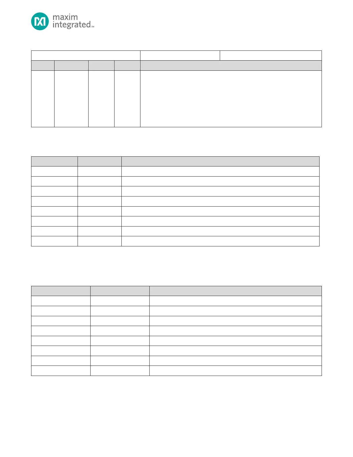
Table 9-8: DMACn Interrupt Register
DMACHn Channel Interrupt Flag
Each bit in this field represents an interrupt for the corresponding channel interrupt
m. To clear an interrupt, clear the corresponding active interrupt bit in the
DMACHn_ST register. An interrupt bit in this field is set only if the corresponding
interrupt enable field is set in the DMAm_CN register. Register bits associated with
unimplemented channels should be ignored.
0: No interrupt
1: Interrupt pending
9.11 DMA Channel Registers
Table 9-9: Standard DMA Channel 0 to Channel 7 Register Summary
9.12 DMAC Channel Registers
See Table 3-1: APB Peripheral Base Address Map for the DMA Peripheral Base Address
Table 9-10: DMACH Channel Registers Summary
DMACHn Channel Configuration Register
DMACHn Channel Status Register
DMACHn Channel Source Register
DMACHn Channel Destination Register
DMACHn Channel Count Register
DMACHn Channel Source Reload Register
DMACHn Channel Destination Reload Register
DMACHn Channel Count Reload Register