EasyManua.ls Logo

Maxim Integrated MAX32665 - Clock Configuration; Table 11-2: ADC Clock Frequency and ADC Conversion Time (�����&#Xdc4 C;�����&#Xdc3 F;�&#Xdc3 E; = 96���&#Xdc3 B;��, ���&#Xdc43

Maxim Integrated MAX32665
457 pages
Print Icon
To Next Page IconTo Next Page
To Previous Page IconTo Previous Page
Loading...
MAX32665-MAX32668 User Guide
Maxim Integrated Page 249 of 457
11.4 Clock Configuration
The ADC clock, adcclk, is controlled by the GCR_PCLK_DIV.adcfrq register field. Configure this field for the target ADC
sample frequency. The maximum clock supported by the ADC is 8MHz. The divisor selection, GCR_PCLK_DIV.adcfrq, for the
ADC depends on the peripheral clock. Equation 11-2 shows the calculation for the ADC clock frequency, where:


.
Equation 11-2: ADC Clock Frequency



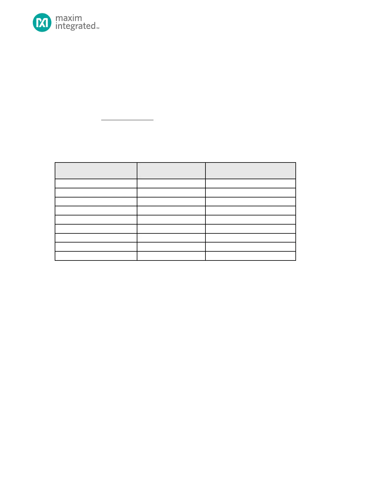
The GCR_PCLK_DIV.adcfrq register field setting must result in a value for

 as shown in Table 11-2 with the
System Clock set as the 96MHz high frequency oscillator.
Table 11-2: ADC Clock Frequency and ADC Conversion Time (

,

)
GCR_PCKDIV.adcfrq[3:0]
ADC Clock Frequency (Hz)

10-Bit Word Conversion Time (s)

0x 0x7
Invalid
Invalid
0x8
6,000,000
171
0x9
5,333,333
192
0xA
4,800,000
214
0xB
4,363,636
235
0xC
4,000,000
256
0xD
3,692,308
278
0xE
3,428,571
299
0xF
3,200,000
320

Table of Contents