MAX32665-MAX32668 User Guide
Maxim Integrated Page 330 of 457
16.3 Timer Pin Functionality
Most timers have an associated timer pin that can function as an optional input or output depending on the selected timer
mode. The timer pin functionality is mapped as an alternate function that is shared with a GPIO. Timer pin assignments are
detailed in the data sheet for the specific device.
When the timer pin alternate function is enabled, the timer pin will have the same electrical characteristics, such as
pullup/pulldown strength, drive strength, etc. as the GPIO mode settings for that pin. When configured as an output, the
corresponding bit in the GPIO_OUT register should be configured to match the inactive state of the timer pin for that mode.
The pin characteristics must be configured before enabling the timer. Consult the GPIO section for details on how to
configure the electrical characteristics for the pin
Each timer has a dedicated interrupt flag, TMRn_INT.irq, which is set at the end of a timer period. If enabled, an interrupt
will be generated. The interrupt flag can be cleared by writing any value to TMRn_INT.irq.
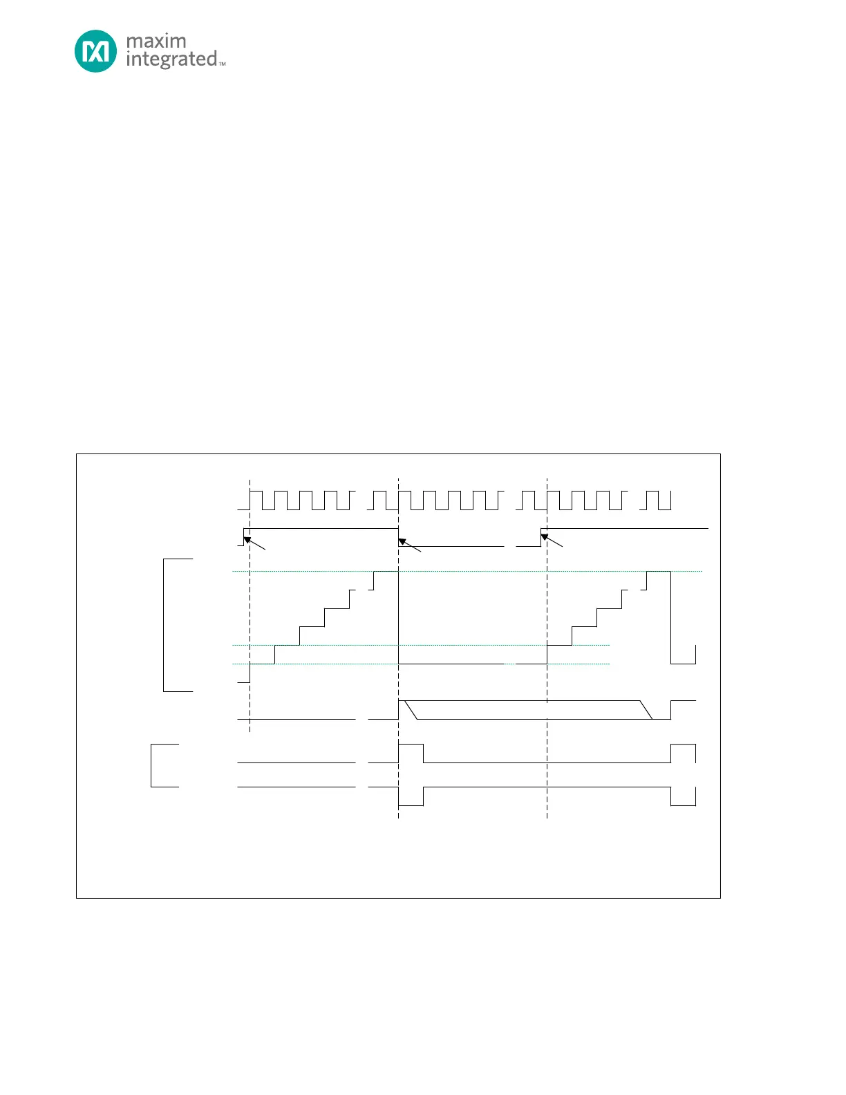
16.4 One-Shot Mode (000b)
In One-shot mode the timer peripheral increments TMRn_CNT until it matches TMRn_CMP and then stops incrementing
and disables the timer. The timer can optionally output a pulse on the timer pin at the end of the timer period. In this
mode, the timer must be re-enabled to start another one-shot mode event.
Figure 16-1: One-Shot Mode Diagram
TMR_CN.TEN
TMR_CNT
0X0000_0000**
0X0000_0001*
TMR_INT.IRQ
TIMER CLOCK
TMR_CMP
* TMR_CNT AUTOMATICALLY RELOADS WITH 0X0000_0001 AT THE END OF THE TIMER PERIOD, BUT SOFTWARE CAN WRITE ANY INITIAL VALUE TO TMR_CNT
BEFORE THE TIMER IS ENABLE D.
** THE DEFAULT VALUE OF TMR_CNT FOR THE FIRS T PE RIOD AFTER A SY STEM RE SET IS 0X0000_0000 UNLESS CHA NGED BY SOFTWARE.
TMR_CN.TPL = 1
TMR_CN.TPL = 0
TIMER PIN
(OUTPUT)
0X0000_0002
TIMER ENABLED
BY SOFTWARE
TIMER DISABLED
BY HARDWARE
TIMER ENABLED
BY SOFTWARE
SOFTWARE CLEARS BIT