MAX32665-MAX32668 User Guide
Maxim Integrated Page 310 of 457
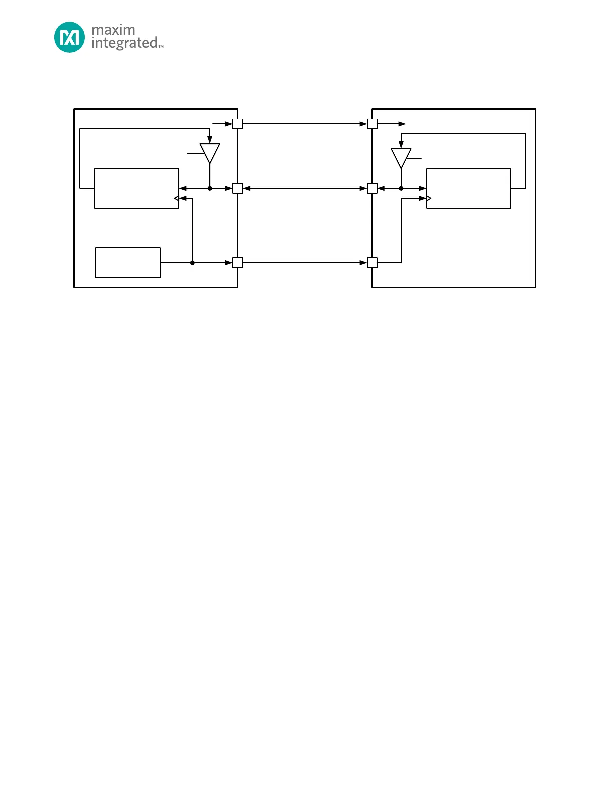
Figure 14-3: Generic 3-Wire SPI Master to Slave Connection
14.3 Pin Configuration
Before configuring the QSPIn peripheral, first disable any SPI activity for the port by setting the QSPIn_CTRL0.enable field to
0.
14.3.1 QSPIn Alternate Function Mapping
Pin selection and configuration is required to use the QSPIn port. The following information applies to SPI master and slave
operation as well as three-wire, four-wire, dual and quad mode communications. Table 14-2 maps standard SPI signal
names to the Alternate Function name. Determine the pins required for the SPI type and mode in the application and
configure the required GPIO as described in the following sections.
The Alternate Function Name column in Table 14-2 maps the standard SPI signal name to the Alternate Function name.
Refer to the data sheet for pin availability for a specific package.
When the QSPIn port is disabled, QSPIn_CTRL0.enable = 0, the GPIO pins enabled for QSPI alternate function are placed in
high-impedance input mode.
14.3.2 Four-wire Format Configuration
Four wire SPI uses SCK, MISO, MOSI, and one or more SS pins. Four wire SPI may use more than one slave select pin for a
transaction, resulting in more than four wires total, however the communication is referred to as four wire for legacy
reasons. The following steps set up QSPI1 for four wire SPI with three Slave Select lines.
Note: QSPI0 provides SPI pins on Alternate Function 1 and Alternate Function 2. Select the pins mapped to the SPI external
device in the design and modify the setup accordingly. There is no restriction on which alternate function is used for a
specific SPI pin and each SPI pin can be used independently from the other pins chosen.
14.3.3 Three-Wire Format Configuration
Three wire SPI uses SCK, MOSI (SOSI) and one or more slave select pins for an SPI transaction. Three-wire SPI configuration
is identical to the four wire configuration except QSPIn_MISO does not need set up for the QSPI alternate function. The
direction of communication in three-wire SPI mode is controlled by the QSPIn Transmit and Receive FIFO enables. Enabling
the Receive FIFO and disabling the Transmit FIFO indicates a read transaction. Enabling the Transmit FIFO and disabling the
Receive FIFO indicates a write transaction. It is an illegal condition to enable both the Transmit and Receive FIFOs in three
wire SPI operation.