MAX32665-MAX32668 User Guide
Maxim Integrated Page 155 of 457
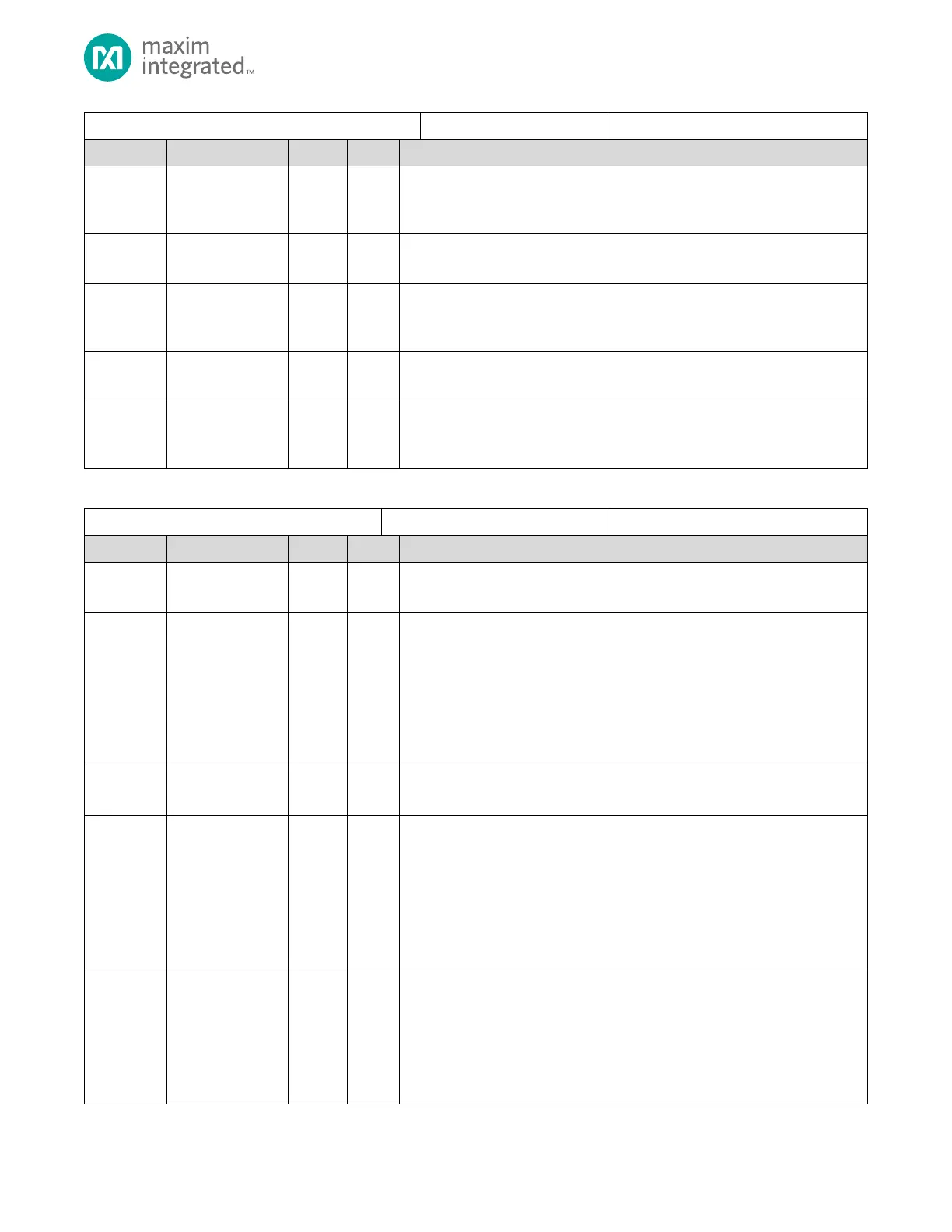
SPIXF Controller FIFO Control and Status Register
Receive FIFO Almost Full Level
The Almost Full flag is asserted when the number of used FIFO entries (bytes)
exceed this value. FIFO depth is 32 bytes.
Reserved for Future Use
Do not modify this field.
Transmit FIFO Entry Count
Current number of used entries (words) in the Transmit FIFO. Writes to this field
are ignored.
Reserved for Future Use
Do not modify this field.
Transmit FIFO Almost Empty Level
The Almost Empty flag is asserted when the number of unused FIFO entries in
words exceeds this value. FIFO depth is 16 words.
Table 8-9. SPIXF Controller Special Control Register
SPIXF Controller Special Control Register
Reserved for Future Use
Do not modify this field.
SCK Inhibit mode 3
In SPI mode 3, some SPI flash read timing diagrams show the last SCK going low
prior to de-assertion. The default is to support this additional falling edge of the
clock. When this bit is set, and the device is in SPI mode 3, the SPI clock is held
high while slave select is de-asserted. This is to support some SPI flash write
timing diagrams.
0: Allow trailing SCK low pulse prior to slave select de-assertion.
1: Inhibit trailing SCK low pulse prior to slave select de-assertion.
Reserved for Future Use
Do not modify this field.
SDIO Output Enable Sample Mode
Defines whether the output is enabled for each SDIO pin.
Bit 11: SDIO[3]
Bit 10: SDIO[2]
Bit 9: SDIO[1]
Bit 8: SDIO[0]
0: SDIO output disabled.
1: SDIO output enabled.
SDIO Output Value Sample Mode
Defines the values for the SDIO outputs when in Sample Mode
(SPIXFC_SP_CTRL.sampl=1).
Bit 7: SDIO[3]
Bit 6: SDIO[2]
Bit 5: SDIO[1]
Bit 4: SDIO[0]