MAX32665-MAX32668 User Guide
Maxim Integrated Page 391 of 457
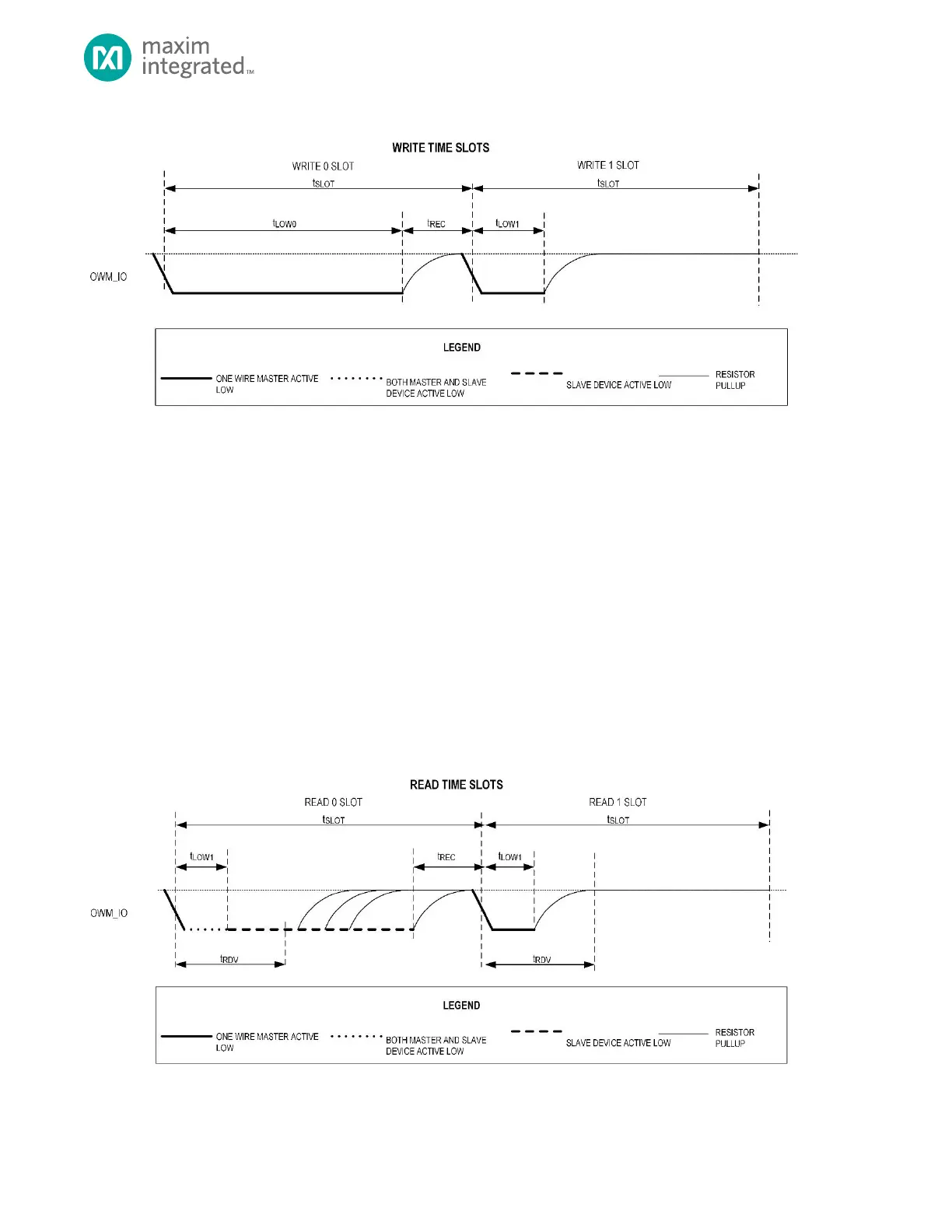
Figure 20-3: 1-Wire Write Time Slot
From the slave’s perspective, the initial falling edge of the time slot triggers the start of an internal timer, and when the
proper amount of time has passed, the slave samples the 1-Wire line that is driven by the master. This sampling point is in
between the end of the minimum-width low pulse and the end of the time slot.
OWM Read Time Slot
As with all 1-Wire transactions, the master initiates all bit read time slots. Like the bit write time slots, the bit read time slot
begins with a falling edge. From the master’s perspective, this time slot is transmitted identically to the "Write 1 Bit" time
slot shown in Figure 20-3. The master begins by transmitting a falling edge, holds the line low for a minimum-width period,
and then releases the line.
The difference here is that instead of the slave sampling the line, the slave begins transmitting either a 0 (by holding the line
low) or a 1 (by leaving the line to float high) after the initial falling edge. The master then samples the line to read the bit
value that is transmitted by the slave device.
As an example, Figure 20-4 shows a sequence in which the slave device transmits data back to the 1-Wire bus master upon
request. Note that to transmit a 1 bit, the slave device does not need to do anything. It simply leaves the line alone (to float
high) and waits for the next time slot. To transmit a 0 bit, the slave device holds the line low until the end of the time slot.
Figure 20-4: 1-Wire Read Time Slot