MAX32665-MAX32668 User Guide
Maxim Integrated Page 374 of 457
compensated are used during the RTC frequency calibration procedure because they incorporate the frequency
adjustments provided by the digital trim function.
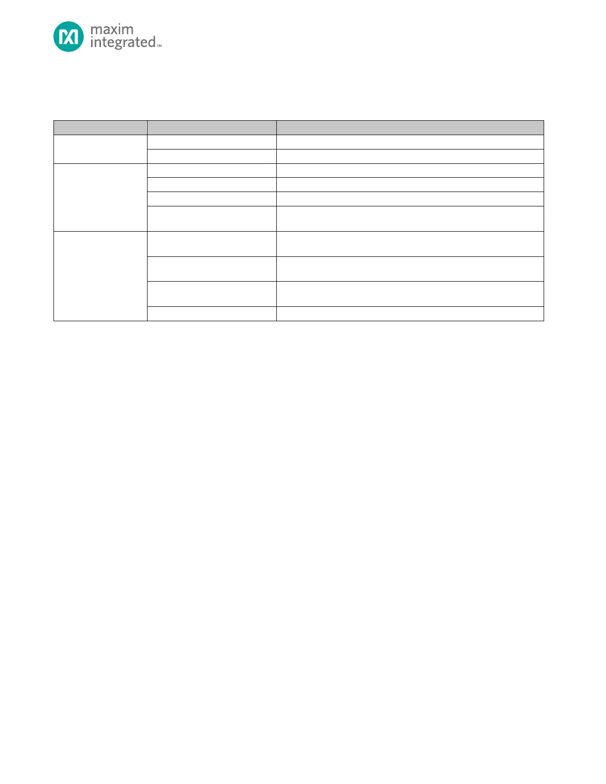
Table 18-3. MAX32665―MAX32668 RTC Square Wave Output Configuration
Use the following procedure to generate the square wave:
Software configures the fields shown in Table 18-3. to select the desired frequency.
If more than one output pin is available, software configures the fields shown in Table 18-3. MAX32665―MAX32668 RTC
Square Wave Output Configuration to select the output pin.
Software configures the fields shown in Table 18-3. to enable the square wave output.
18.5 RTC Calibration
A digital trim facility provides the ability to compensate for RTC inaccuracies of up to ± 127ppm when compared against an
external reference clock. The trimming function utilizes an independent, dedicated timer which increments the sub-second
register based on a user-supplied, 2’s compliment value in the RTC_TRIM register as shown in Figure 18-4. Internal
Implementation of Digital Trim, 4kHz.