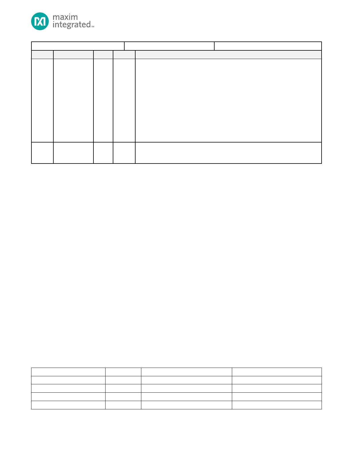
V
COREB
Switch
VCOREB can be operated at a lower voltage to minimize leakage in any of the low
power modes SLEEP, DEEPSLEEP, and BACKUP. Allows the CPU cores to operate from
VCOREA during these low power modes.
0b00: Reserved for Future Use
0b01: CPU0, CPU1 operate from VCOREA in low power mode. When VCOREB reaches
operating voltage during exit from low power mode, firmware sets this and the device
switches to operate the cores from VCOREB.
0b10: CPU0, CPU1 operate from VCOREA in low power mode. When VCOREB is less
than VCOREA, firmware sets this and the device switches back to a low power mode
0b11: Automatically set by hardware to swicth the CPU0, CPU1 cores to VCOREB.
4.11 Single Inductor Multiple Output (SIMO) Power Supply
The Single Inductor Multiple Output (SIMO) switch mode power supply allows the device to operate autonomously from a
single lithium cell. The SIMO provides four buck switching regulators (V
REGO_A
thru V
REGO_D
). Each of the four regulator
voltages can be controlled by the CPU individually. For the SIMO top operate properly, the four buck regulator outputs
must drive the power supply pins of the device as follows in Table 4-19.
4.11.1 Power Supply Monitor
The system also provides a power monitor that monitors the external power supplies relative to the on-chip bandgap
voltage. The following power supplies are monitored:
• VCOREA (V
COREA
) Digital Core Supply Voltage A for the Always-On Domain
• VCOREB (V
COREB
) Digital Core Supply Voltage B
• VDDIO (V
DDIO
) GPIO Supply Voltage
• VDDIOH (V
DDIOH
) GPIO High Supply Voltage
• VDDA (V
DDA
) AOD Analog Supply Voltage
• VREGI (V
REGI
) Input Supply Voltage, Battery
• VDDB (V
DDB
) USB Supply Voltage
• VTXOUT (V
TXOUT
) Bluetooth Transmitter Supply Voltage Output
• VRXOUT (V
RXOOUT
) Bluetooth Receiver Supply Voltage Output
Each of the power supply monitors’ settings are found in the Low Power Control register PWRSEQ_LPCN. When the
corresponding power monitor is enabled, the input voltage pin is constantly monitored. If the voltage drops below the
trigger threshold, all registers and peripherals in that power domain are reset. This improves reliability and safety by
guarding against a low voltage condition corrupting the contents of the registers and the device state.
Refer to the data sheet electrical characteristics for the trigger threshold values and power fail reset voltages.
Table 4-19: SIMO Power Supply Device Pin Connectivity