MAX32665-MAX32668 User Guide
Maxim Integrated Page 381 of 457
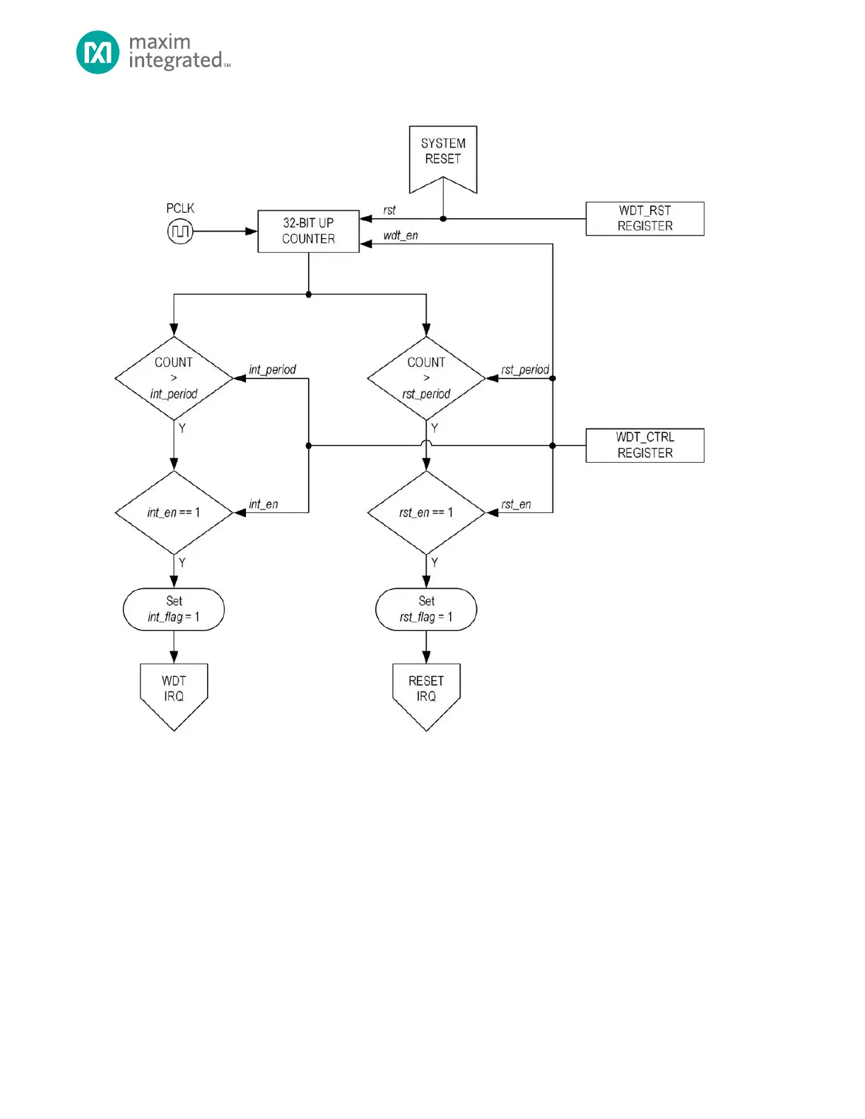
Figure 19-1: Watchdog Timer Block Diagram
19.1 Features
• Sixteen programmable time periods for the watchdog interrupt 2
16
through 2
31
PCLK cycles
• Sixteen programmable time periods for the watchdog reset 2
16
through 2
31
PCLK cycles
• The watchdog timer counter is reset on all forms of reset
19.2 Usage
Utilizing the watchdog timer in the application software is straightforward. As early as possible in the application software,
enable the watchdog timer interrupt and watchdog timer reset. Periodically the application software must write to the
WDT_RST register to reset the watchdog counter. If program execution becomes lost, the watchdog timer interrupt will
occur, giving the system a “last chance” to recover from whatever circumstance caused the improper code execution. The
interrupt routine may either attempt to repair the situation or allow the watchdog timer reset to occur. In the event of a
system software failure, the interrupt will not be executed, and the watchdog system reset will recover operation.