MAX32665-MAX32668 User Guide
Maxim Integrated Page 264 of 457
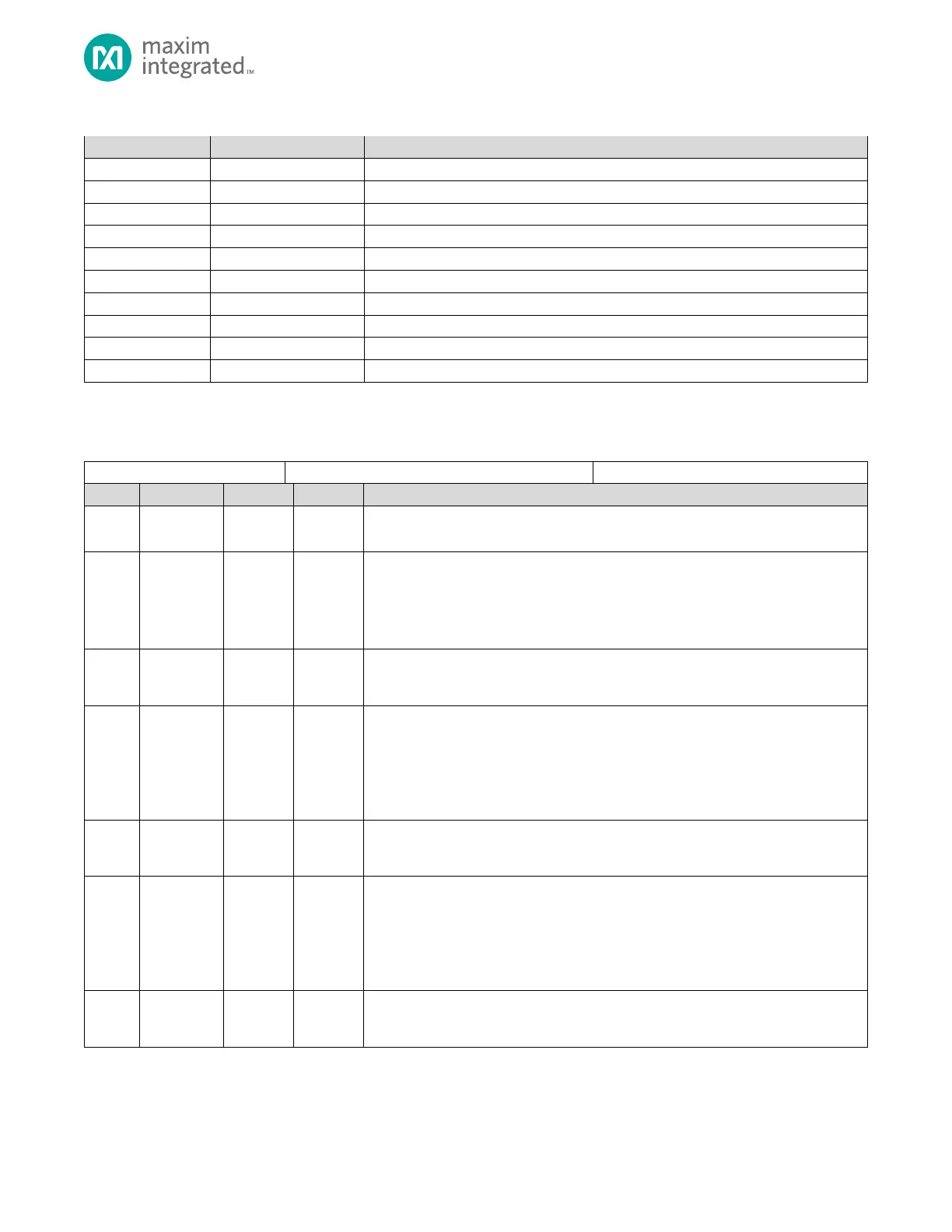
Table 12-3: UART Register Summary
UARTn Interrupt Enable Register
UARTn Interrupt Flag Register
UARTn Baud Rate Integer Register
UARTn Baud Rate Decimal Register
UARTn FIFO Read/Write Register
UARTn DMA Configuration Register
UARTn Transmit FIFO Register
12.10 Register Details
Table 12-4: UART Control 0 Register
Reserved for Future Use
Do not modify this field.
Receive Timeout Frame Count
Represents the number of frames to wait for a character. If the Receive FIFO contains
data, a Receive Timeout condition occurs if the number of frames in this register
passes without the FIFO receiving any new data. If a timeout occurs, the hardware sets
the receive timeout flag to 1 (UARTn_INT_FL.rx_to = 1).
Bit Rate Clock Source Select
0:
1:
.
Transmit BREAK
Set this field to 1 to set the TX line low during a character transmission. A character
must be transmitting for this feature to operate. The Tx line remains low until this field
is set to zero.
0: Normal UART operation.
1: Transmit zero during a character transfer.
Null Modem Support
0: Normal operation for RTS/CTS and TX/RX
1: Null Modem Mode: RTS/CTS swapped, TX/RX swapped
RTS/CTS Polarity
This field controls the polarity used for the RTS/CTS signals. Setting this field to 0
indicates active low assertion for the signals. Setting this field to 1 uses an active high
assertion.
0: RTS/CTS asserted is 0
1: RTS/CTS asserted is 1
Hardware Flow Control Enable
0: Hardware flow control disabled.
1: Hardware RTS/CTS flow control enabled.