MAX32665-MAX32668 User Guide
Maxim Integrated Page 197 of 457
LED Control
1: LED on
0: LED off
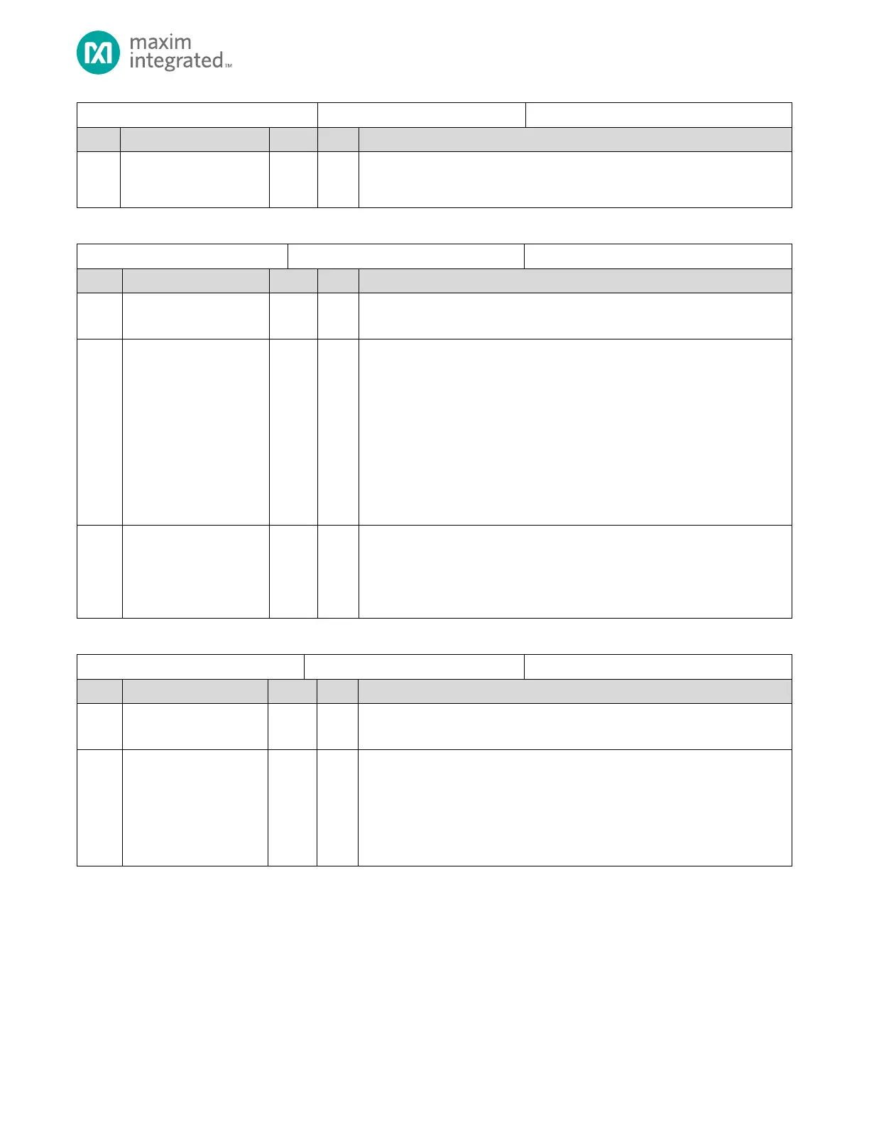
Table 8-67: SDHC Power Control Register
Reserved for Future Use
Do not modify this field.
SD Bus Voltage Select
Sets the voltage level for the SD card. Validate the setting against the Capabilities
Register (SDHC_CFG_0).
7: 3.3V typical
6: 3.0V typical
5: 1.8V typical
4: Reserved for Future Use.
3: Reserved for Future Use.
2: Reserved for Future Use.
1: Reserved for Future Use.
0: Reserved for Future Use.
SD Bus Power
Before setting this bit, configure the SDHC_PWR.bus_volt_sel field. If no card is
detected, then this bit is automatically set to 0 by the SDHC.
1: Power Enabled
0: Power Disabled
Table 8-68: SDHC Block Gap Control Register
Block Gap Control Register
Reserved for Future Use
Do not modify this field.
Interrupt at Block Gap
Setting this bit to 1 enables interrupt detection at the block gap for a multiple
block transfer.
1: Enabled
0: Disabled
Note: This bit is only valid if SDHC_PWR.data_transfer_width=1 (4-bit mode).