MAX32665-MAX32668 User Guide
Maxim Integrated Page 316 of 457
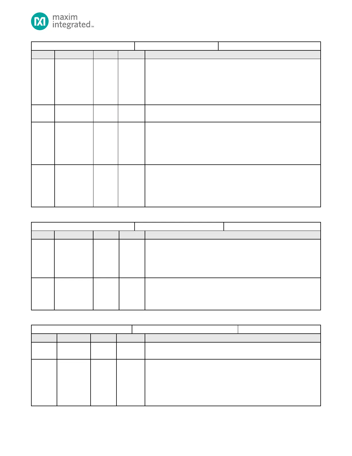
Master Slave Select Signal Direction
Set the I/O direction for
0: Slave Select is an output
1: Slave Select is an input
Note: This field is only used when the QSPIn is configured for Master Mode
(QSPIn_CTRL0.mm_en = 1).
Reserved for Future Use
Do not modify this field.
SPI Master Mode Enable
This field selects between slave mode and master mode operation for the SPI
port. Write this field to 0 to operate as an SPI slave. Setting this field to 1 sets the
port as an SPI master.
0: Slave mode SPI operation.
1: Master mode SPI operation.
SPI Enable/Disable
This field enables and disables the QSPIn port. Disable the QSPIn port by setting
this field to 0. Disabling the QSPIn port does not affect the QSPIn FIFOs or register
settings.
0: QSPIn port is disabled
1: QSPIn port is enabled
Table 14-9: QSPIn Transmit Packet Size Register
QSPIn Transmit Packet Size Register
Number of Receive Characters
Number of characters to receive in RX FIFO.
Note: If the QSPIn port is set to operate in 4-wire mode, this field is ignored and
the QSPIn_CTRL1.tx_num_chars field is used for both the number of characters to
receive and transmit.
Number of Transmit Characters
Number of characters to transmit from TX FIFO.
Note: If the QSPIn port is set to operate in 4-wire mode, this field is used for both
the number of characters to receive and transmit.
Table 14-10: QSPIn Control 2 Register
Reserved for Future Use
Do not modify this field.
Slave Select Polarity
Controls the polarity of each individual SS signal where each bit position
corresponds to a SS signal. QSPIn_SS0 is controlled with bit position 0 and
QSPIn_SS2 is controlled with bit position 2.
For each bit position,
0: SS is active low
1: SS is active high