MAX32665-MAX32668 User Guide
Maxim Integrated Page 346 of 457
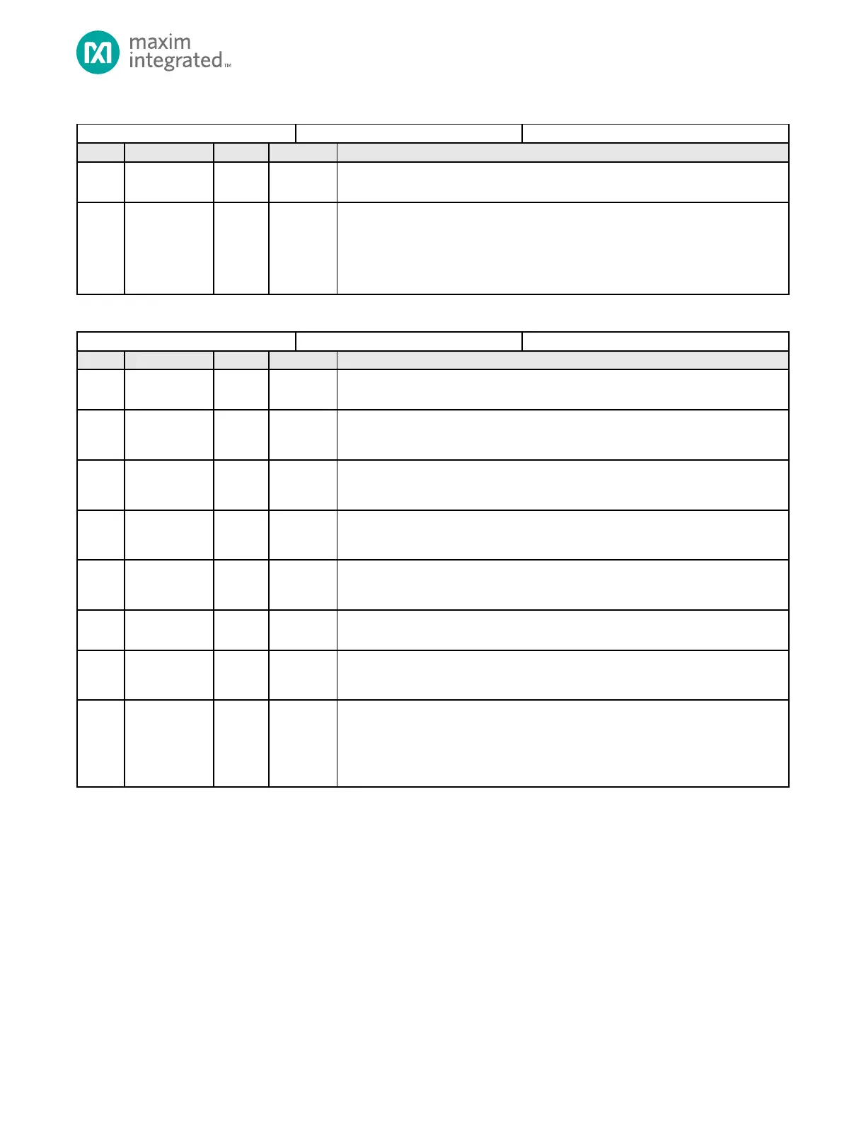
Table 16-4: Timer Interrupt Registers
Reserved for Future Use
Do not modify this field from its default value.
Timer Interrupt
If set, this field indicates a timer interrupt condition occurred.
Writing any value to this bit clears the timer’s interrupt.
0: Timer interrupt is not active.
1: Timer interrupt occurred.
Table 16-5: Timer Control Registers
Reserved for Future Use
Do not modify this field from its default value.
PWM Output
Disable
1: Disable PWM Output
0: Enable PWM Output
PWM Output
Polarity Bit
1: Output
inverted
0: Output
non-inverted
PWM Output
Polarity Bit
1: Output
inverted
0: Output
non-inverted
PWM Synchronization Mode
1: PWM synchronization mode enabled
0: PWM synchronization mode disabled
Timer Prescale Select MSB
See TMRn_CN.pres for details on this field’s usage.
Timer Enable
1: Timer enabled
0: Timer disabled
Timer Polarity
Selects the polarity of the timer’s input and output signal. This setting is not used if
the GPIO is not configured for the alternate function. The tpol field meaning is
determined by the specific mode of the timer. See the mode’s detailed configuration
section for tpol usage.