MAX32665-MAX32668 User Guide
Maxim Integrated Page 399 of 457
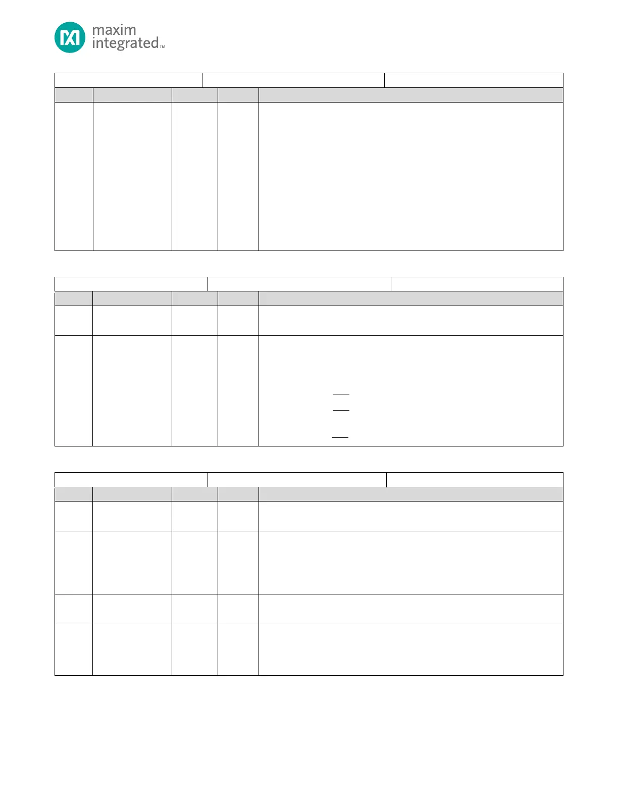
OWM Configuration Register
Long Line Mode Enable
Selects alternate timings for 1-Wire communication. The recommended setting
depends on the length of the wire. For lines less than 40 meters, 0 should be
used.
Setting this bit to 0 leaves the write one release, the data sampling, and the
time-slot recovery times at approximately 5μs, 15μs, and 7μs, respectively.
Setting this bit to 1 enables long line mode timings during standard mode
communications. This mode moves the write one release, the data sampling,
and the time-slot recovery times out to approximately 8μs, 22μs, and 14μs,
respectively.
0: Standard operation for lines less than 40 meters.
1: Long line mode enabled, see description above.
Table 20-6: OWM Clock Divisor Register
OWM Clock Divisor Register
Reserved for Future Use
Do not modify this field.
OWM Clock Divisor
Divisor for the OWM peripheral clock. The target is to achieve a 1MHz clock. See
the Clock Configuration section for details.
0x00: OWM clock disabled.
0x01:
0x02:
. . .
0xFF:
Table 20-7: OWM Control/Status Register
OWM Control/Status Register
Reserved for Future Use
Do not modify this field.
Presence Detect Flag
Set to 1 when a presence pulse is detected from one or more slaves during the
1-Wire reset sequence.
0: No presence detect pulse during previous 1-Wire reset sequence.
1: Presence detect pulse on bus during previous 1-Wire reset sequence.
Overdrive Spec Mode
Returns the version of the overdrive spec.
OWM_IN State
Returns the current logic level on the OWM_IO pin.
0: OWM_IO pin is low.
1: OWM_IO pin is high.