MAX32665-MAX32668 User Guide
Maxim Integrated Page 340 of 457
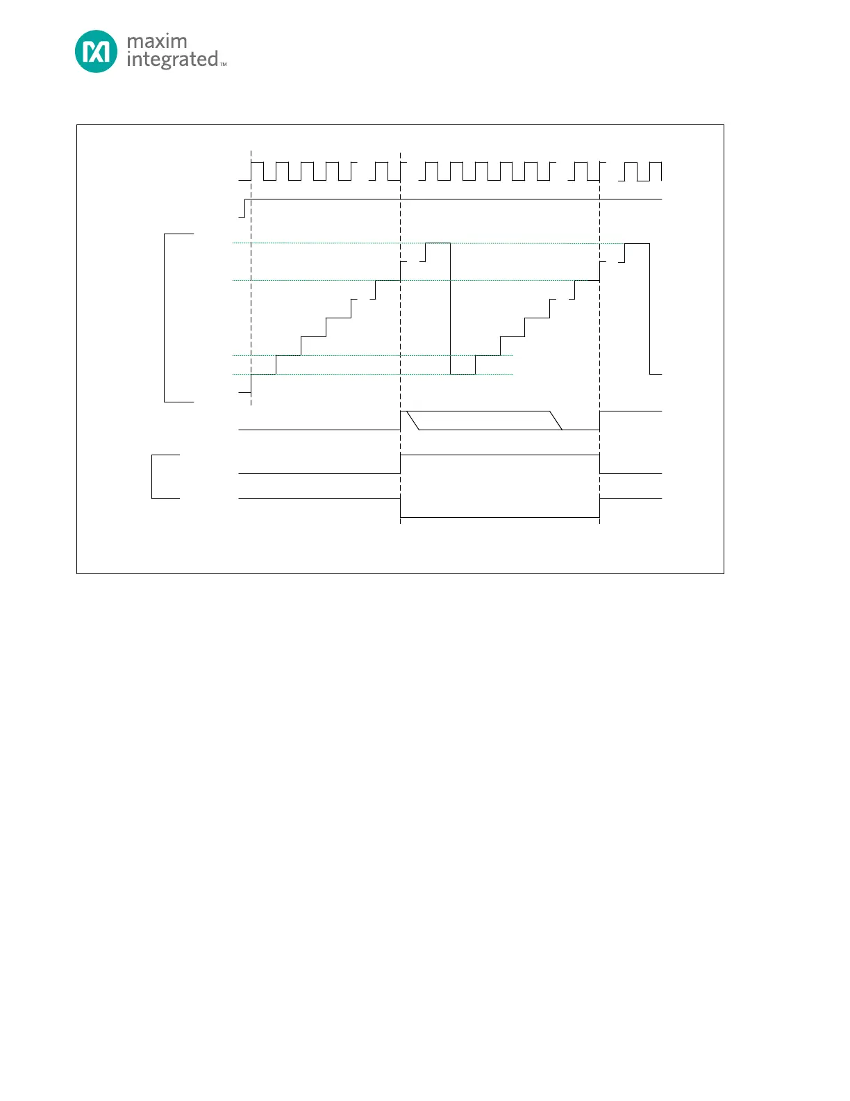
Figure 16-5: Counter Mode Diagram
TMR_CN.ten
TMR_CNT
0x0000 0000**
0x00 00 0001*
TMR_INT.irq
TIMER CLOCK
f
CNT_CLK
TMR_CMP.cmp
* TM R_CNT AUTOMATICALLY RELOADS WITH 0x0000 0001 AT THE END OF THE TIMER PERIOD. FIRMWARE SETS THE INITIAL VALUE FOR TMR_CNT
BEFORE THE TIMER IS ENABLE D.
** THE DEFAULT VALUE OF TMR_CNT FOR THE FIRST P ERIOD AFTER A SY STEM RESET IS 0 x0000_0000 UNLESS CHANGED BY S OFTWARE.
FIRMWARE CLEARS TMR_INT.irq BIT
0xFFFF FFFF
TMR_CN.tpol = 1
TMR_CN.tpol = 0
TIMER OUTPUT
PIN
0x0000 0002
16.9.1 Compare Mode Timer Period
The timer period ends on the timer clock following TMRn_CNT = TMRn_CMP.
The timer peripheral automatically performs the following actions at the end of the timer period:
1. The timer remains enabled and continues incrementing. Unlike other modes, TMRn_CNT is not reset to
0x0000 0001 at the end of the timer period.
2. If the timer output is enabled, then the timer pin toggles state (low to high or high to low).
3. The timer interrupt bit TMRn_INT.irq will be set. An interrupt is generated if enabled.