MAX32665-MAX32668 User Guide
Maxim Integrated Page 234 of 457
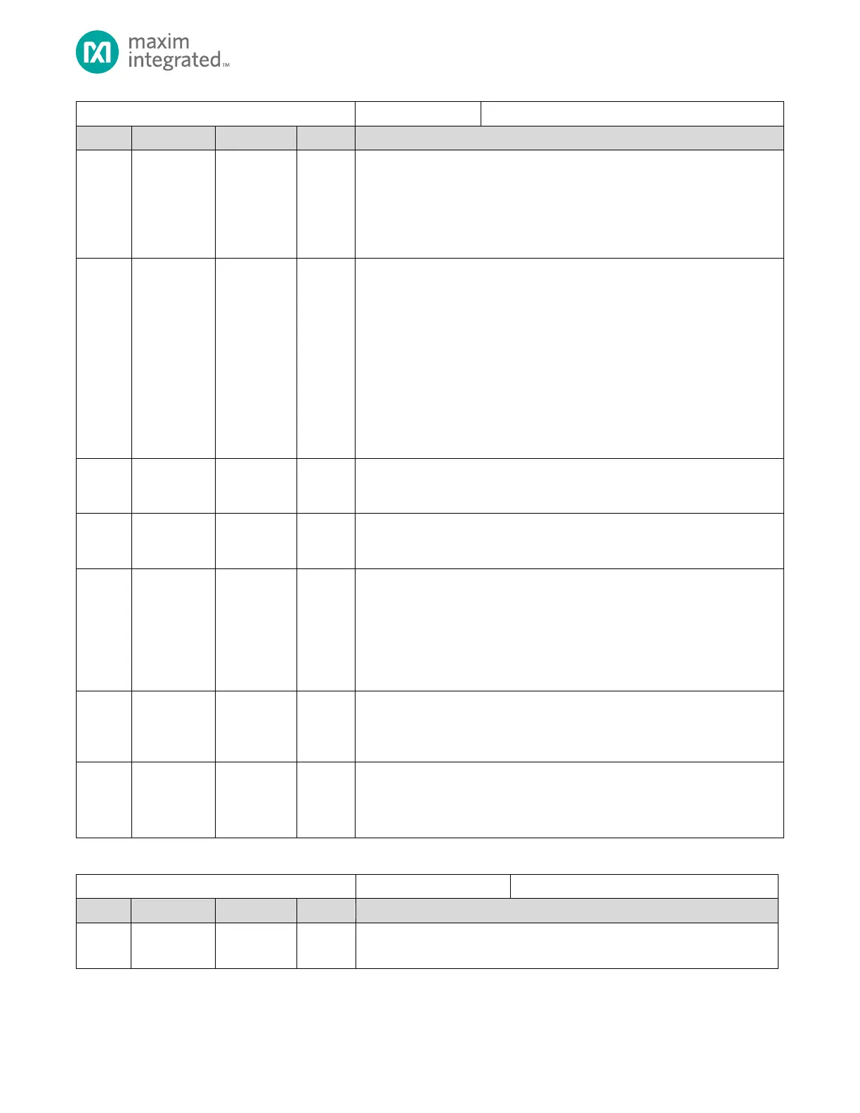
DMA Channel n Configuration
Timeout Timer Clock Pre-Scale Select
Selects the Pre-Scale divider for the timer clock input.
0x0: Timer disabled.
0x1: f
HCLK
/ 2
8
0x2: f
HCLK
/ 2
16
0x3: f
HCLK
/ 2
24
Timeout Period Select
Selects the number of pre-scaled clocks seen by the channel timer before a
timeout condition is generated. The value is approximate because of
synchronization delays between timers
0: 3-4
1: 7-8
2: 15-16
3: 31-32
4: 63-64
5: 127-128
6: 255-256
7: 511-512
Request DMA Timeout Timer Wait Enable
0: Start timer immediately when enabled.
1: Delay timer start until after the first DMA transaction occurs.
Request Select
Selects the source and destination for the transfer as shown in Table 9-2:
MAX32665—MAX32668 DMAC Source and Destination by Peripheral.
Channel Priority
Sets the priority of the channel relative to other channels of DMAm. Channels of
the same priority are serviced in a round-robin fashion.
0x0: Highest priority
0x1: …
0x2: …
0x3: Lowest priority
Reload Enable
Setting this bit to 1 allows reloading the DMACHn_SRC, DMACHn_DST, and
DMACHn_CNT registers with their corresponding reload registers upon CTZ.
Note: This bit is also writeable in the DMAn_CNT_RLD register.
Channel Enable
This bit is automatically cleared when DMACHn_ST.ch_st changes from 1 to 0.
0: Disabled
1: Enabled
Table 9-12: DMA Status Register
Reserved for Future Use
Do not modify this field from its reset default value.