MAX32665-MAX32668 User Guide
Maxim Integrated Page 293 of 457
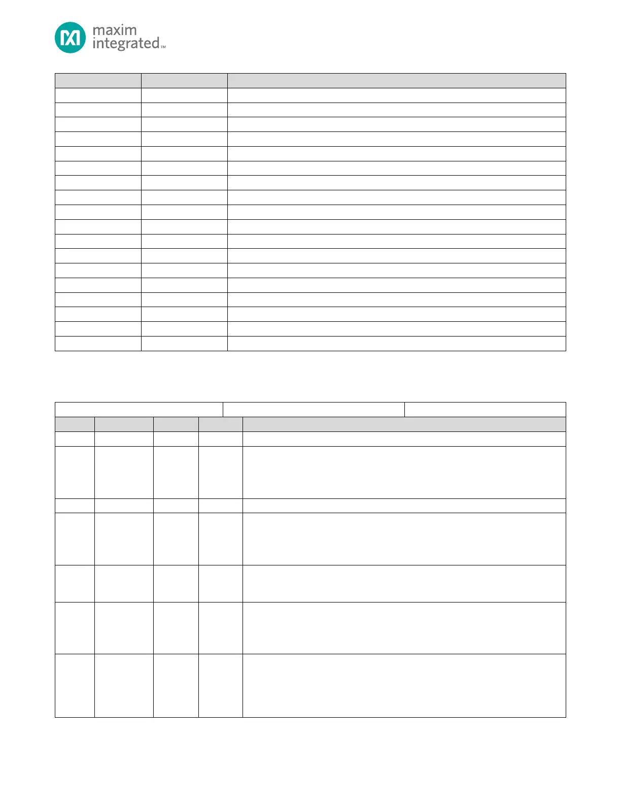
I
2
C Interrupt Flags 0 Register
I
2
C Interrupt Enable 0 Register
I
2
C Interrupt Flags 1 Register
I
2
C Interrupt Enable 1 Register
I
2
C Receive Control 0 Register
I
2
C Receive Control 1 Register
I
2
C Transmit Control 0 Register
I
2
C Transmit Control 1 Register
I
2
C Transmit and Receive FIFO Register
I
2
C Clock Low Time Register
I
2
C Clock High Time Register
I
2
C Hs-Mode Clock Control Register
I
2
C Slave Address Register
13.6 Register Details
Table 13-6: I
2
C Control 0 Register
Hs-Mode Enable
I
2
C high speed mode operation
0: Disable
1: Enable
Single Master Only
When set to 1, the device MUST ONLY be used in a single master application with
slave devices that are NOT going to hold SCL low (i.e. the slave devices will never
clock stretch)
Slave Mode Clock Stretching
0: Enabled
1: Disabled
Slave Read/Write Bit Status
Returns the logic level of the R/W bit on a received address match
(I2Cn_INT_FL0.ami = 1) or general call match (I2Cn_INT_FL0.gci = 1). This bit is valid
three sys_clk clock cycles after the address match status flag is set.
Software Output Control Enabled
Setting this field to 1 enables software bit-bang control of I
2
C.
0: The I2C controller manages the SDA and SCL pins in hardware.
1: SDA and SCL are controller by firmware using the I2Cn_CTRL0.sdao and
I2Cn_CTRL0.sclo fields.