MAX32665-MAX32668 User Guide
Maxim Integrated Page 251 of 457
11.7.1 AIN0 – AIN7 Scale Limitations
The external inputs, AIN0 through AIN7, support scaling of the input by 50%, the reference by 50%, or both by 50%. Also,
the scaling can further be modified by additional factors of 2, 3, or 4 as defined by ADC_CTRL.adc_divsel. The scale settings
for the given input signal and reference must satisfy the following equation to be valid:
Equation 11-3: Input and Reference Scale Requirements Equation
11.7.2 Scale Limitations for All Other Input Channels
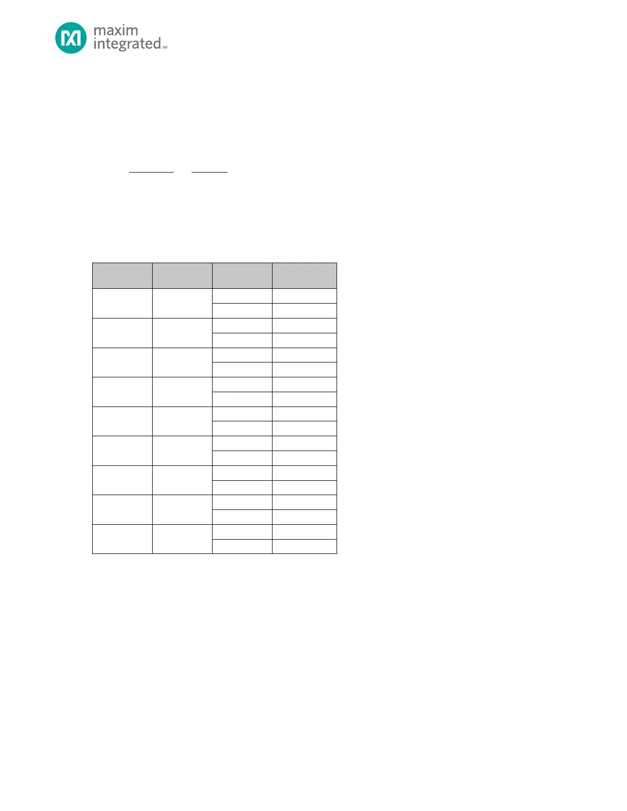
For the remaining internal input channels, the scale settings must either both be disabled, or both be enabled as shown in
Table 11-3, below.
Table 11-3: Input and Reference Scale Support by ADC Input Channel
11.7.3 Data Conversion Output Alignment
The ADC outputs a total of 10-bits per conversion and stores the data in the DATA register LSB justified by default. Table
11-4 shows the ADC data alignment based on the value of the ADC_CTRL.data_align bit.