MAX32665-MAX32668 User Guide
Maxim Integrated Page 416 of 457
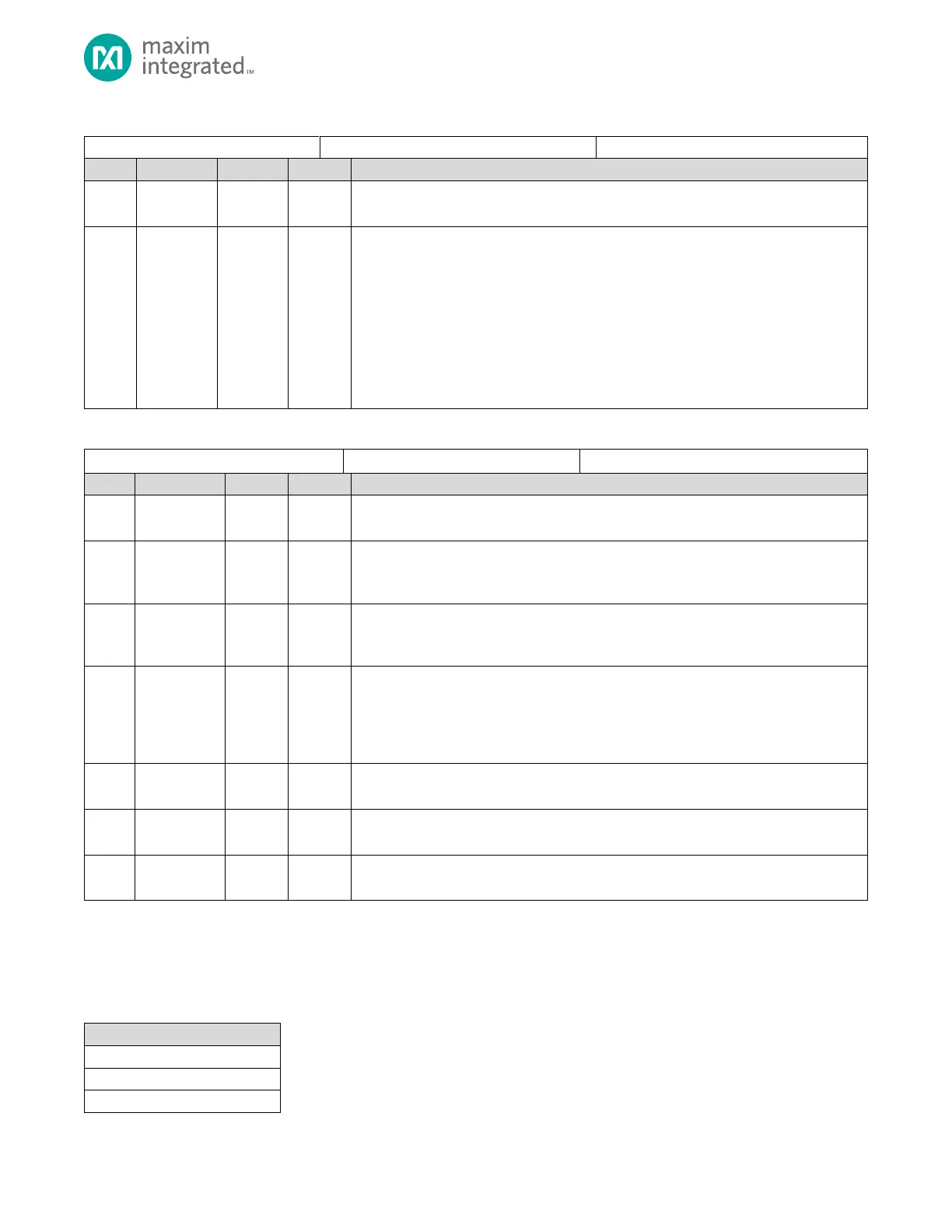
Table 21-15: USBHS Register Index Select Register
USBHS Register Index Select
Reserved for Future Use
Do not modify this field.
Index Register Access Selector
Each IN and OUT endpoint has memory-mapped control and status registers in addresses
from 0x400B 1010 to 0x400B 1018. Only one endpoint’s registers are addressable in the
memory map at time. This bit field selects which endpoint’s registers are present in the
memory map where:
0x0: Endpoint 0 IN/OUT status registers addressable.
0x1: Endpoint 1 IN/OUT status registers addressable.
0x2: Endpoint 2 IN/OUT status registers addressable.
…
0xB: Endpoint 11 IN/OUT status registers addressable.
Table 21-16: USBHS Test Mode Register
Reserved for Future Use
Do not modify this field.
Force FS Mode
When the USBHS receives a RESET from the Host, the USBHS is forced into Full-Speed
mode.
Force HS Mode
When the USBHS receives a RESET from the Host, the USBHS is forced into Hi-Speed
mode.
Test Packet Mode
To enter this test mode, firmware must write the standard 53-byte test packet to the
Endpoint 0 FIFO, then set USBHS_INCSRL.inpktrdy = 1, then set this bit. The DATA0 PID is
automatically added to the head of the packet and the CRC to the end of the packet. The
USBHS will continue to send the test packet until this bit is cleared.
HS Data K State Test Mode
The USBHS transmits a continuous Data K State
HS Data J State Test Mode
The USBHS transmits a continuous Data J State
SE0 NAK Test Mode
The USBHS responds to any valid IN token with a NAK
21.12.2 Endpoint Register Access Control
Each IN and OUT endpoint from Endpoint 0x1 to 0xB uses memory mapped access to the registers in Table 21-17. Selecting
a specific endpoint, using the USBHS_INDEX register, maps each of the registers in Table 21-17 to the selected endpoint.
Table 21-17: USB Memory Mapped Register Access for Endpoints 1 to 11