MAX32665-MAX32668 User Guide
Maxim Integrated Page 253 of 457
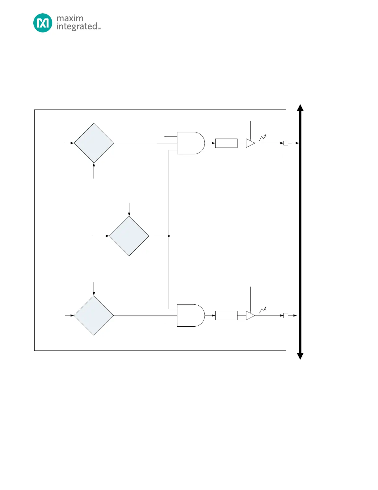
11.7.5 Data Limits and Out of Range Interrupts
Channel limits are implemented to minimize power consumption for power supply monitoring. The ADC includes four limit
registers, ADC_LIMIT0 to ADC_LIMIT3, that you can use to set a high limit, low limit, and the ADC channel number to apply
the limits against. A block diagram of the limit engine for each of the four limit registers is shown in Figure 11-2.
Figure 11-2: ADC Limit Engine
A
B
ADC_CTRL
adc_ch_sel
ADC_LIMITn
ch_sel
A
B
ADC_LIMITn
ch_lo_limit
ADC_DATA
adc_data
A
B
ADC_LIMITn
ch_hi_limit
ADC_DATA
adc_data
ADC_LIMITn
ch_hi_limit_en
ADC_LIMITn
ch_lo_limit_en
ADC SYSTEM
INTERRUPT
ADC_INTR
adc_lo_limit_ie
ADC SYS TEM
INTERRUPT
ADC_INTR
adc_hi_limit_ie
APB
ADC_INTR
adc_hi_limit_if
ADC_INTR
adc_lo_limit_if
NOTE: ADC_LIMITn indicates a single limit register, either ADC_LIMIT0, ADC_LIMIT1, ADC_LIMIT2 or ADC_LIMIT3. Each
limit registe r includes a dedicated ADC limit engine.
A > B
OVER LIMIT
COMPARE
A = B
CHANNEL
COMPARE
A < B
UNDER LIMIT
COMPARE
LIMIT CONTROL ENGINE
When a measurement is taken on the ADC, the limit engine determines if the channel measured matches one of the
channels selected by the limit registers. If it does and the data converted is above or below the high or low limit, an
interrupt flag is set resulting in an ADC interrupt if the interrupt is enabled.