MAX32665-MAX32668 User Guide
Maxim Integrated Page 373 of 457
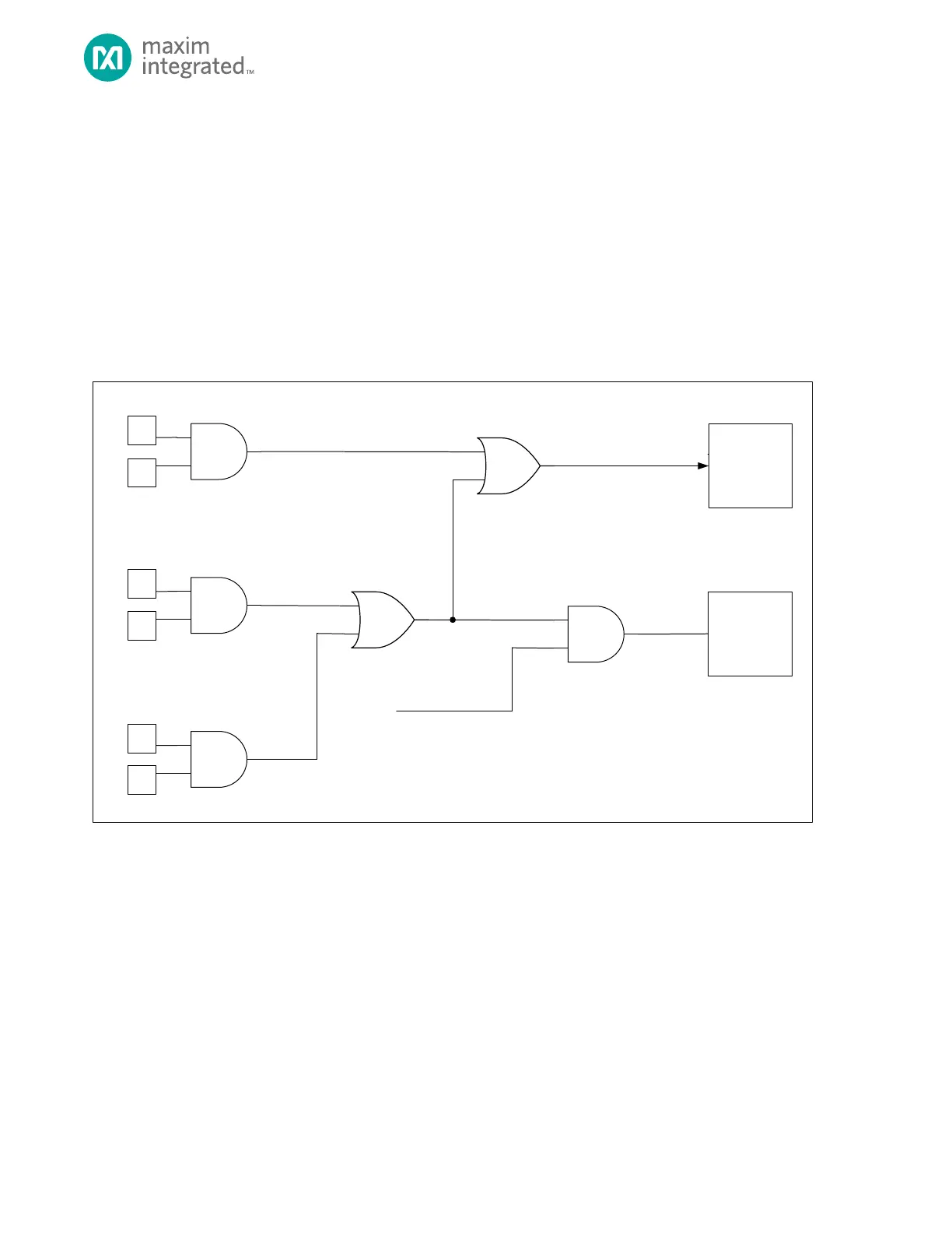
18.4.3 RTC Interrupt and Wakeup Configuration
The following are a list of conditions that, when enabled, can generate an RTC interrupt.
• Time-of-Day Alarm
• Sub-second Alarm
• Ready field asserted high, signaling write access permitted
RTC can be configured so the Time-of-day and sub-second alarms are a wakeup source for exiting the following low power
modes:
• Backup
• Deepsleep
Figure 18-3. RTC Interrupt/Wakeup Diagram Wakeup Function
Use this procedure to enable the RTC as a wakeup source:
1. Software configures the RTC interrupt enable bits so one or more interrupt conditions will generate an RTC
interrupt.
2. Create a RTC IRQ handler function and register the address of the RTC IRQ handler using the NVIC.
3. Software sets GCR_PMR.rtcwken to 1 to enable the system wakeup for by the RTC.
4. Software places the device into the desired low power mode. Refer to section Operating Modes for details on
entering DEEPSLEEP or BACKUP mode.
18.4.4 Square Wave Output
The RTC can output a 50% duty cycle square wave signal derived from the 32kHz oscillator on a selected device pin. Refer to
Table 18-3. for the device pins, frequency options, and control fields specific to this device. Frequencies noted as