MAX32665-MAX32668 User Guide
Maxim Integrated Page 392 of 457
20.3.1.2.2 Standard Speed and Overdrive Speed
By default, all 1-Wire communications following reset begin at the lowest rate of speed (that is, standard speed). For 1-Wire
devices that support it, it is possible for the OWM to increase the rate of communication from standard speed to overdrive
speed by sending the appropriate command.
The protocols and time slots operate identically for standard and overdrive speeds. The difference comes in the widths of
the time slots and pulses. The OWM automatically adjusts the timings based on the setting of the OWM_CFG.overdrive
field.
If a 1-Wire slave device receives a standard speed reset pulse, it resets and reverts to standard speed communication. If the
device is already communicating in overdrive mode, and it receives a reset pulse at the overdrive speed, it resets but
remains in overdrive mode.
20.3.1.3 ROM Commands (Network Layer)
Following the initial 1-Wire reset pulse on the bus, all slave 1-Wire devices are active, which means that they are monitoring
the bus for commands. Because the 1-Wire bus can have multiple slave devices present on the bus at any time, the OWM
must go through a process (defined by the 1-Wire command protocol) to activate only the 1-Wire slave device that it
intends to communicate with and deactivate all others. This is the purpose of the ROM commands (network layer) shown in
Table 20-2.
Table 20-2: 1-Wire ROM Commands
The ROM command layer relies on the fact that all 1-Wire slave devices are assigned a globally-unique, 64-bit ROM ID. This
ROM ID value is factory programmed to ensure that no two 1-Wire slave devices have the same value.
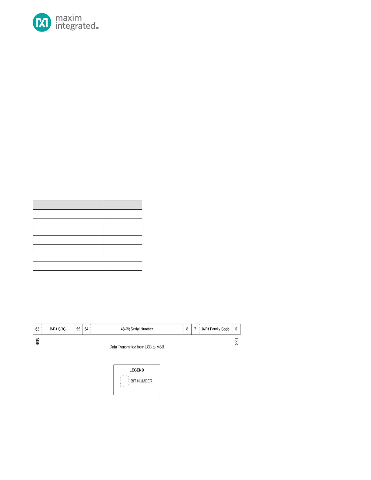
Figure 20-5 is a visual representation of the 1-Wire ROM ID fields and shows the organization of the fields within the 64-bit
ROM ID for a device.
Figure 20-5: 1-Wire ROM ID Fields
Table 20-3 provides a detailed description of each of the ROM ID fields.