MAX32665-MAX32668 User Guide
Maxim Integrated Page 309 of 457
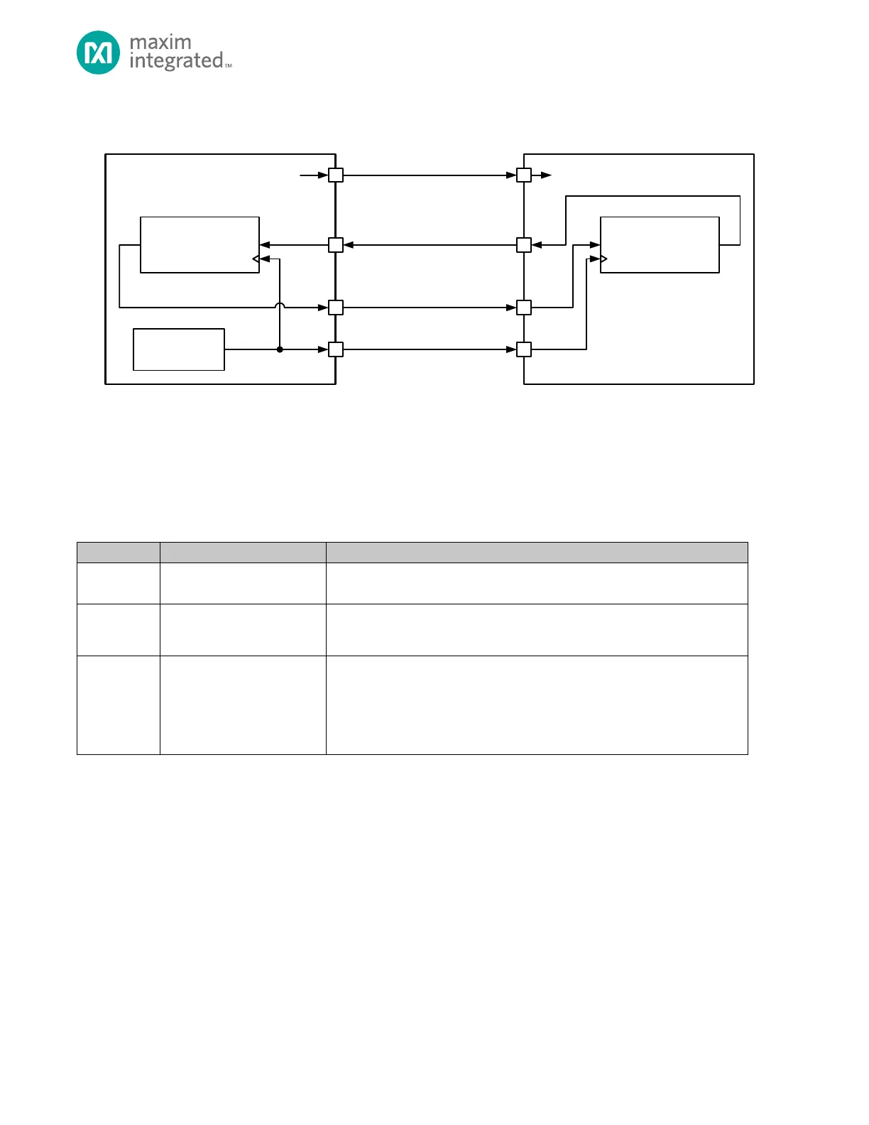
Figure 14-2: 4-Wire SPI Connection Diagram
14.2.2 Three-Wire SPI
The signals in three-wire SPI operation are shown in Table 14-4: Three-Wire Format Signals, The MOSI signal is used as a bi-
directional, half-duplex I/O referred to as Slave Input Slave Output (SISO). Three-wire SPI also uses a serial clock signal
generated by the master and a slave select pin controlled by the master.
Table 14-4: Three-Wire Format Signals
The master generates the serial clock signal, which is an output from the
master and an input to the slave.
This is a half-duplex, bidirectional I/O pin used for communication between the
SPI master and. This signal is used to transmit data from the master to the
slave and to receive data from the slave by the master.
In master mode, this signal is an output used to select a slave device prior to
communication.
In slave mode QSPIn_SS0 is a dedicated input which indicates an external
master is going to start communication. Other slave select signals into the
peripheral are ignored in slave mode
A three-wire SPI network is shown in Figure 14-3, below. The master device selects the slave device using the slave select
output. The communication starts with the master asserting the slave select line and then starting the clock (SCK). In
three-wire SPI communication, the master and slave must both know the intended direction of the data to prevent bus
contention. For a write, the master drives the data out the SISO pin. For a read, the master must release the SISO line and
let the slave drive the SISO line, usually on the second edge of a clock cycle. The direction of transmission is controlled using
the FIFO. Writing to the FIFO starts the three-wire SPI write and reading from the FIFO starts a three-wire SPI read
transaction.