MAX32665-MAX32668 User Guide
Maxim Integrated Page 370 of 457
18.2 Instances
One instance of the RTC peripheral is provided.
The RTC counter and alarm registers are shown in Table 18-1. MAX32665―MAX32668 RTC Counter and Alarm Registers.
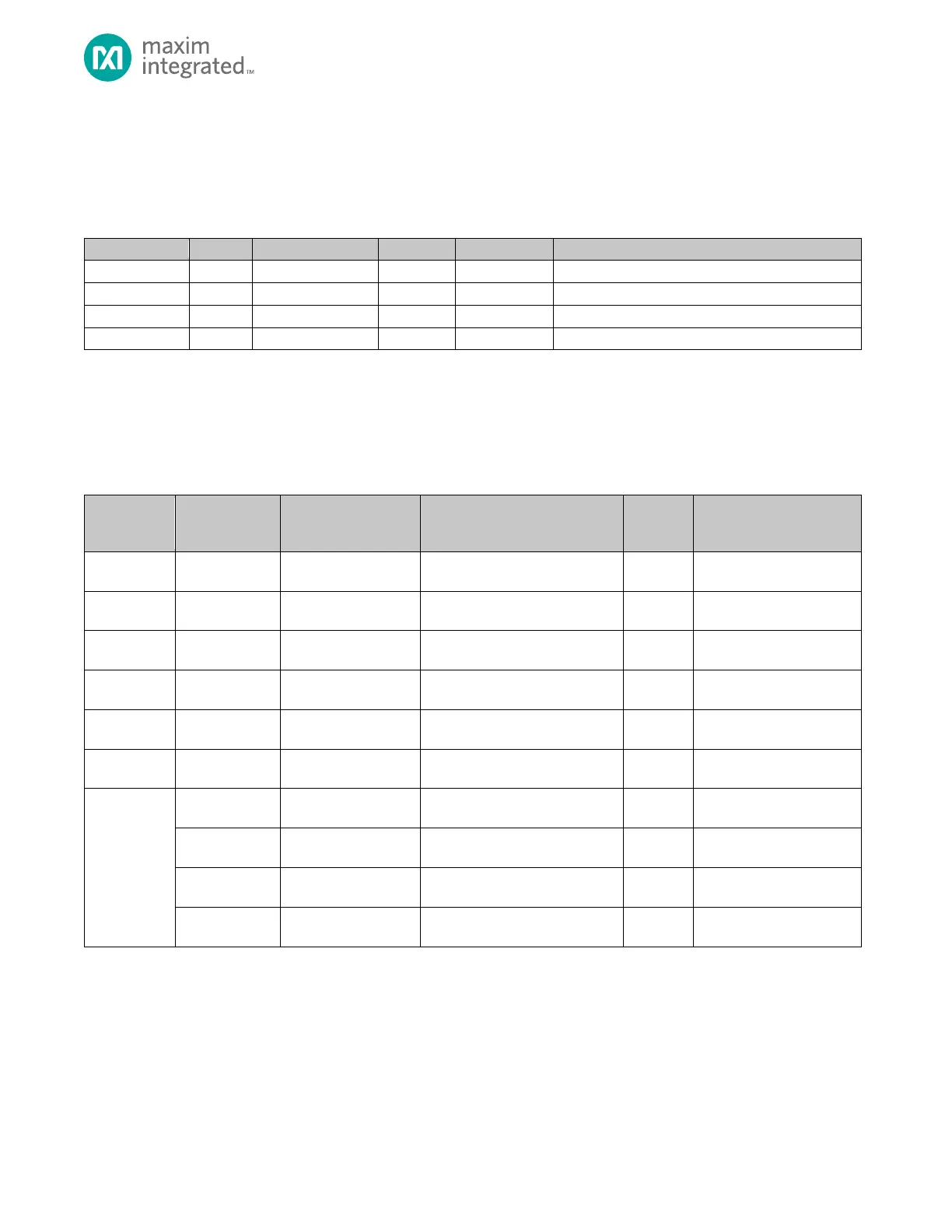
Table 18-1. MAX32665―MAX32668 RTC Counter and Alarm Registers
Sub-Seconds Counter Register
Time-of-Day Alarm Register
Sub-Second Alarm Register
18.3 Register Access Control
Access protection mechanisms prevent software from accessing critical registers and fields while RTC while hardware is
updating them. Monitoring the RTC_CTRL.busy and RTC_CTRL.ready fields allows software to determine when it is safe to
write to registers and when registers will return valid results.
Table 18-2. RTC Register Access
RTC_CTRL.busy = 0
RTC_CTRL.ready = 1
RTC_CTRL.busy = 0
RTC_CTRL.ready = 1
RTC_CTRL.busy = 0
RTC_CTRL.ready = 1
RTC_CTRL.busy = 0
RTC_CTRL.ready = 1
Sub-Seconds Counter
Register
RTC_CTRL.busy = 0
RTC_CTRL.tod_alarm_en = 0
Time-of-Day Alarm Register
RTC_CTRL.busy = 0
RTC_CTRL.ssec_alarm_en = 0
Sub-Second Alarm Register
RTC_CTRL.busy = 0
RTC_CTRL.write_en = 1
RTC_CTRL.busy = 0
RTC_CTRL.write_en = 1
Oscillator Control Register
RTC_CTRL.busy = 0
RTC_CTRL.write_en = 1
Time-of-Day Alarm enable
field
Sub-Second Alarm enable
field
18.3.1 RTC_SEC and RTC_SSEC Read Access Control
Software reads of the RTC_SEC and RTC_SSEC registers will return invalid results if the read operation occurs on the same
cycle that the register is being updated by hardware. To avoid this, hardware clears RTC_CTRL.ready to 0 during the update
cycle and sets RTC_CTRL.ready to 1 again when the cycle is complete. The period of the RTC_CTRL.ready bit set/clear
activity provides a large window during which the count registers are readable.