MAX32665-MAX32668 User Guide
Maxim Integrated Page 163 of 457
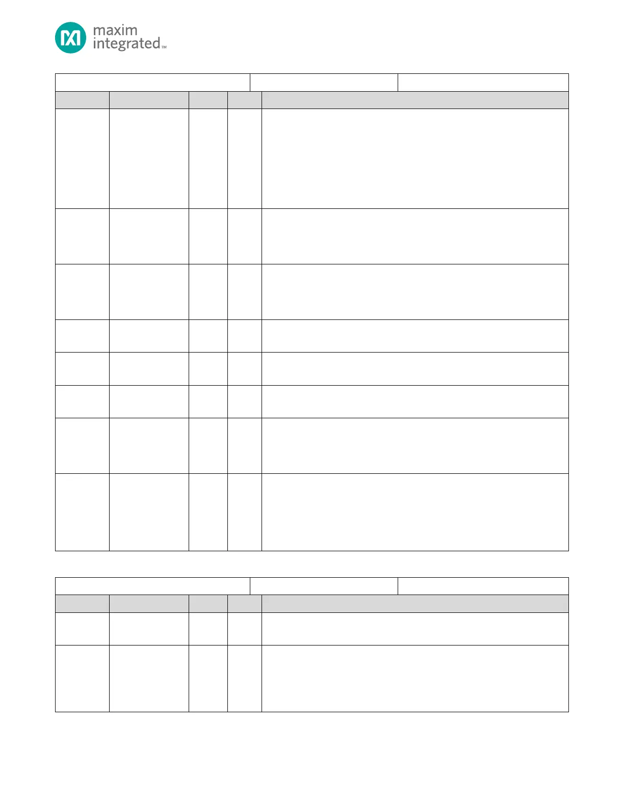
SPIXFM Configuration Register
Slave Select Active Timing
Controls delay from assertion of slave select to start of the SCK pulse and delay
from the end of SCK pulses to de-assertion of slave select. See 8.2.1.1.6, above,
for details on slave select transaction delay configuration.
0b00: 0 system clocks
0b01: 2 system clocks
0b10: 4 system clocks
0b11: 8 system clocks
SCK High Clocks
Number of system clocks that SCK is held high when SCK pulses are generated.
0: Invalid
All other values: The number of system clocks that SCK is held high.
SCK Low Clocks
Number of system clocks that SCK is held low when SCK pulses are generated.
0: Invalid
All other values: The number of system clocks that SCK is held low.
Reserved for Future Use
Do not modify this field.
Slave Select
Only valid value is zero
Reserved for Future Use
Do not modify this field.
Slave Select Polarity
This bit controls the polarity of the slave select.
0: Slave Select active high
1: Slave Select active low
SPI mode
Set this field to the required SPI mode.
0b00: SPI mode 0
0b01: Reserved
0b10: Reserved
0b11: SPI mode 3
Table 8-17. SPIXFM Fetch Control Register
SPIXFM Fetch Control Register
Reserved for Future Use
Do not modify this field.
Four-Byte Address mode
Enables 4-byte Flash Address mode. Defaults to value as defined by parameter
in instantiation. User can override.
0: 3-byte address mode
1: 4-byte address mode