EasyManuals Logo

Maxim Integrated MAX32665 User Manual

Maxim Integrated MAX32665
457 pages
To Next Page IconTo Next Page
To Previous Page IconTo Previous Page
Page #143 background imageLoading...
Page #143 background image
MAX32665-MAX32668 User Guide
Maxim Integrated Page 143 of 457
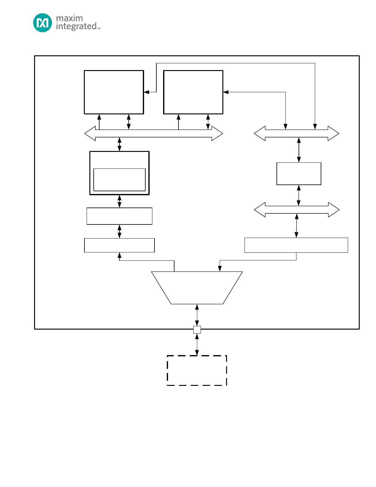
Figure 8-1. Simplified SPIXF Block Diagram
I D
ARM
®
Cortex
®
-M4
CPU1
AHB
SPIXF CACHE
CONTROLLER (SFCC)
SYSTEM BUS
MEMORY DECRYPTION
INTEGRITY UNIT
SPIXF MASTER INTERFACE
EXTERNAL
SPI-XIP FLA SH
16KB
INSTRUCTION
CACHE
ARM
®
Cortex
®
-M4
CPU0
I D
AHB2APB
SYNC ÷ 2
APB 0
BUS 0
f
PCLK
=
f
SYS_CLK
÷ 2
SPIXF M ASTER CONTROLLER
INTERFACE
READ/WRITE
READ PA TH
WRITE PATH
8.2.1 SPIXF Master Controller
The SPIXF Master Controller block (SPIXFC) shown in Figure 8-2 consists of transmit and receive shift registers (supported by
FIFOs) and a control unit. Communication and interface configuration are set up using the APB registers. It contains one
16×16 FIFO (Transmit FIFO) to support the transmit direction and one 32×8 FIFO (Receive FIFO) to support the receive
direction. These FIFOs are accessible to firmware using an AHB interface to support high-speed data transfers. New data is
moved automatically from the Transmit FIFO into the shift register at the start of every new SPI transfer as long as there is

Table of Contents

Questions and Answers:

Question and Answer IconNeed help?

Do you have a question about the Maxim Integrated MAX32665 and is the answer not in the manual?

Maxim Integrated MAX32665 Specifications

General IconGeneral
BrandMaxim Integrated
ModelMAX32665
CategoryMotherboard
LanguageEnglish