MAX32665-MAX32668 User Guide
Maxim Integrated Page 390 of 457
touch contact interface), which means that it is the master’s responsibility to poll the bus as needed to determine the
number and types of 1-Wire devices that are connected to the bus.
All communication sequences on the 1-Wire Bus are initiated by the OWM. The OWM determines when 1-Wire data
transmissions begin, as well as the overall communication speed that is used. There are three different communication
speeds supported by the 1-Wire specification: standard speed, overdrive speed, and hyperdrive speed. However, only
standard speed and overdrive speed are supported by the OWM peripheral in the devices.
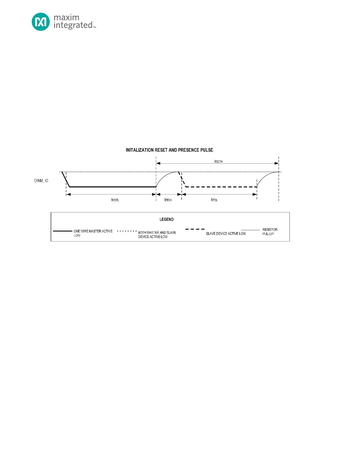
The OWM begins each communication sequence by sending a reset pulse as shown in Figure 20-2. This pulse resets all 1-
Wire slave devices on the line to their initial states and causes them all to begin monitoring the line for a command from
the OWM. Each 1-Wire slave device on the line responds to the reset pulse by sending out a presence pulse. These pulses
from multiple 1-Wire slave devices are combined in wired-AND fashion, resulting in a pulse whose length is determined by
the slowest 1-Wire slave device on the bus.
Figure 20-2: 1-Wire Reset Pulse
In general, the 1-Wire line must idle in a high state when communication is not taking place. It is possible for the master to
pause communication in between time slots. There is no overall "timeout" period that causes a slave to revert to the reset
state if the master takes too long between one time slot and the next time slot.
The 1-Wire communication protocol relies on the fact that the maximum allowable length for a bit transfer (write 0/1 or
read bit) time slot is less than the minimum length for a 1-Wire reset. At any time, if the 1-Wire line is held low (by the
master or by any slave device) for more than the minimum reset pulse time, all slave devices on the line interpret this as a
1-Wire reset pulse.
20.3.1.2.1 Read and Write Time Slots
OWM Write Time Slot
All 1-Wire bit time slots are initiated by the 1-Wire bus master and begin with a single falling edge. There is no indication
given by the beginning of a time slot whether a read bit or write bit operation is intended, as the time slots all begin in the
same manner. Rather, the 1-Wire command protocol enforces agreement between the OWM and slave as to which time
slots are used for bit writes and which time slots are used for bit reads.
When multiple bits of a value are transmitted (or read) in sequence, the least significant bit of the value is always sent or
received first. The 1-Wire bus is a half-duplex bus, so data is transmitted in only one direction (from master to slave or from
slave to master) at any given time.
As shown in Figure 20-3, the time slots for writing a 0 bit and writing a 1 bit begin identically, with the falling edge and a
minimum-width low pulse sent by the master. To write a one bit, the master releases the line after the minimum low pulse,
allowing it to be pulled high. To write a zero bit, the master continues to hold the line low until the end of the time slot.