MAX32665-MAX32668 User Guide
Maxim Integrated Page 80 of 457
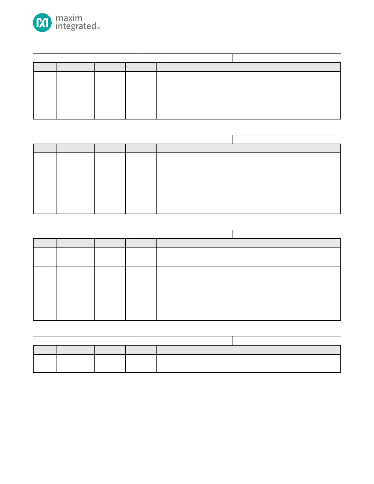
Table 4-43: GPIO0 Low Power Wakeup Status Flags
GPIO0 Low Power Wakeup Status Flags
GPIO0 Pin Wakeup Status Flag
Whenever a GPIO0 pin, in any power mode, transitions from low-to-high or
high-to-low, the corresponding bit in this register is set.
The device will transition from a low-power to ACTIVE mode if the
corresponding interrupt enable bit is set in PWRSEQ_LPWKEN0. This register
should be cleared before entering any low power mode.
Table 4-44: GPIO0 Low Power Wakeup Enable Registers
GPIO0 Low Power Wakeup Enable
GPIO0 Pin Wakeup Interrupt Enable
Setting a bit in this register will cause an interrupt be generated and will wakeup
the device from any low power mode to ACTIVE mode if the corresponding bit in
the PWRSEQ_LPWKST0 register is set. Bits corresponding to unimplemented
GPIO are ignored.
Note: To enable the device to wakeup from a low power mode on a GPIO pin
transition, first set the “GPIO Wakeup enable” register bit
GCR_PMR.gpiowken = 1.
Table 4-45: GPIO1 Low Power Wakeup Status Flags
GPIO1 Low Power Wakeup Status Flags
Reserved
Do not modify this field.
GPIO1 Pin Wakeup Status Flag
Whenever a GPIO0 pin, in any power mode, transitions from low-to-high or
high-to-low, the corresponding bit in this register is set. Bits corresponding to
unimplemented GPIO are ignored.
The device will transition from a low-power to ACTIVE mode if the
corresponding interrupt enable bit is set in PWRSEQ_LPWKEN1. This register
should be cleared before entering any low power mode.
Table 4-46: GPIO1 Low Power Wakeup Enable Registers
GPIO1 Low Power Wakeup Enable
Reserved
Do not modify this field.