MAX32665-MAX32668 User Guide
Maxim Integrated Page 138 of 457
7.5 Flash Controller Register Details
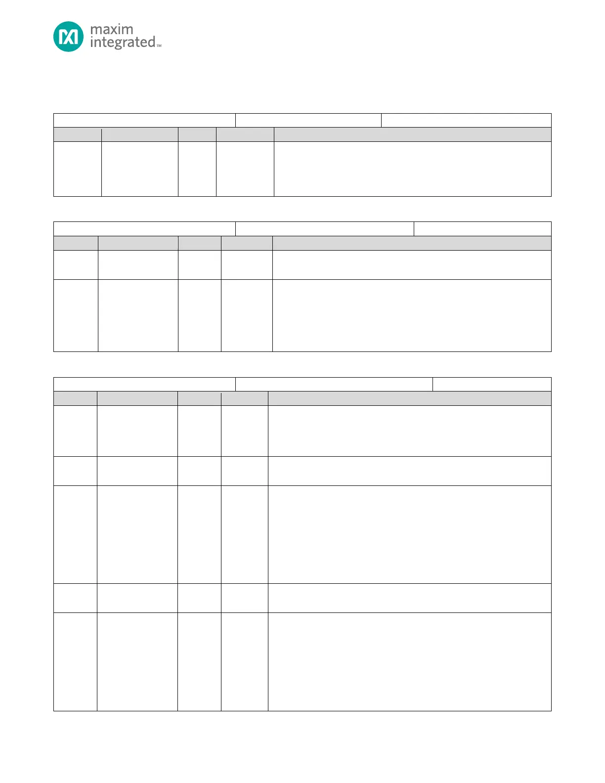
Table 7-4: Flash Controller Address Pointer Register
Flash Address
This field contains the target address for a write operation. A valid internal
flash memory address is required for all write operations.
The reset value for this field is always 0x0010 0000.
Table 7-5: Flash Controller Clock Divisor Register
Flash Controller Clock Divisor Register
Reserved for Future Use
Do not modify this field.
Flash Controller Clock Divisor
The system clock, SYS_CLK, is divided by the value in this field to generate
the FLCn peripheral clock, f
FLCnCLK
. The FLCn peripheral clock must equal
1MHz. The default on all forms of reset is 96 (0x60), resulting in
f
FLCnCLK
= 1MHz. The FLCn peripheral clock is only used during erase and
program functions and not during read functions.
Table 7-6: Flash Controller Control Register
Flash Controller Control Register
Flash Unlock
Write the unlock code, 0x2, prior to any flash write or erase operation to
unlock the Flash. Writing any other value to this field locks the internal flash.
0x2: Flash unlock code
Reserved for Future Use
Do not modify this field.
Flash Busy Flag
When this field is set, writes to all flash registers except the FLCn_INTR
register are ignored by the Flash Controller.
Note: If the Flash Controller is busy (FLCn_CTRL.busy = 1), reads, writes and
erase operations are not allowed and result in an access failure
(FLCn_CTRL.access_fail = 1).
0: Flash idle
1: Flash busy
Reserved for Future Use
Do not modify this field.
Erase Code
Prior to an erase operation this field must be set to 0x55 for a page erase or
0xAA for a mass erase. The flash must be unlocked prior to setting the erase
code.
This field is automatically cleared after the erase operation is complete.
0x00: Erase disabled.
0x55: Page erase code.
0xAA: Enable mass erase.