MAX32665-MAX32668 User Guide
Maxim Integrated Page 73 of 457
Reserved
Reserved. Do not modify this field.
Reserved
Reserved. Do not modify this field.
4.13 Single Inductor Multiple Output (SIMO) Registers Details
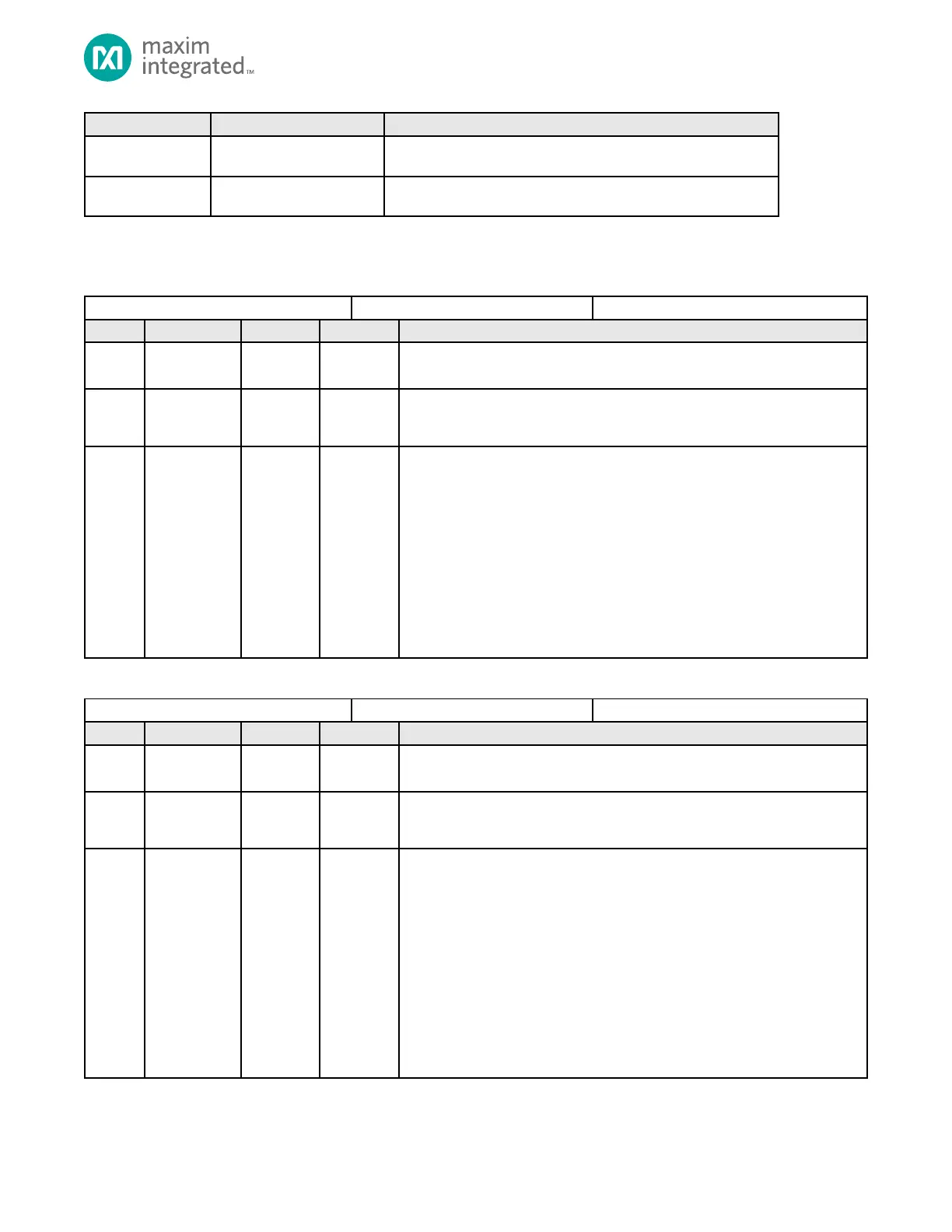
Table 4-21: Buck Voltage Regulator A Control Register
Buck Voltage Regulator A Control
Reserved
Do not modify this field.
Regulator Output Range
0: 0.5V to 1.77
1: 0.6V to 1.87V
Regulator Output Voltage
Each increment in the register represents 10mV.
rangea = 1:
rangea = 0:
Default: 0x78h = 1.7V when rangea = 0; 1.8V when rangea = 1
Warning: When this regulator is connected as shown in SIMO Power
Supply Device Pin Connectivity:
A: The maximum setting for this regulator must be followed for V
DDA
as
indicated in the device datasheet.
B: Setting the regulator to a voltage below the Power-Fail Reset Voltage
for V
DDA
will initiate the Power Monitor Reset Action.
Table 4-22: Buck Voltage Regulator B Control Register
Buck Voltage Regulator A Control
Reserved
Do not modify this field.
Regulator Output Range
0: 0.5V to 1.77
1: 0.6V to 1.87V
Regulator Output Voltage
Each increment in the register represents 10mV.
rangeb = 1;
rangeb = 0;
0x7Fh: 1.77V when rangeb = 0; 1.87V when rangeb = 1
Default: 0x32h = 1.0V when rangeb = 0; 1.1V when rangeb = 1
Warning: When this regulator is connected as shown in SIMO Power
Supply Device Pin Connectivity:
A: The maximum setting for this regulator must be followed for V
COREB
as
indicated in the device datasheet.
B: Setting the regulator to a voltage below the Power-Fail Reset Voltage
for V
COREB
will initiate the Power Monitor Reset Action.