EasyManuals Logo

Maxim Integrated MAX32665 User Manual

Maxim Integrated MAX32665
457 pages
To Next Page IconTo Next Page
To Previous Page IconTo Previous Page
Page #122 background imageLoading...
Page #122 background image
MAX32665-MAX32668 User Guide
Maxim Integrated Page 122 of 457
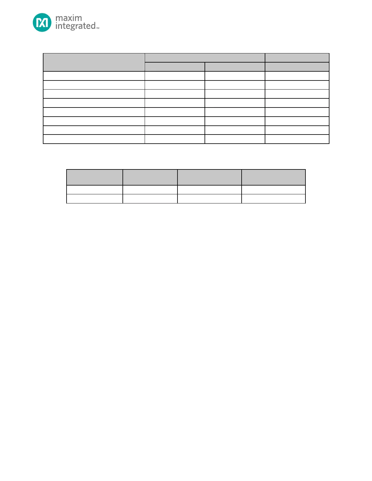
Table 6-5: MAX32665MAX32668 Output Mode Configuration
Input Mode
Drive Strength
Power Supply
GPIOn_DS_SEL1[pin]
GPIOn_DS_SEL0[pin]
GPIOn_VSSEL[pin]
Output Drive Strength 0, V
DDIO
Supply
0
0
0
Output Drive Strength 1, V
DDIO
Supply
0
1
0
Output Drive Strength 2, V
DDIO
Supply
1
0
0
Output Drive Strength 3, V
DDIO
Supply
1
1
0
Output Drive Strength 0, V
DDIOH
Supply
0
0
1
Output Drive Strength 1, V
DDIOH
Supply
0
1
1
Output Drive Strength 2, V
DDIOH
Supply
1
0
1
Output Drive Strength 3, V
DDIOH
Supply
1
1
1
Each GPIO port is assigned a dedicated interrupt vector as shown in the following table.
Table 6-6: MAX32665MAX32668 GPIO Port Interrupt Vector Mapping
GPIO Interrupt Source
GPIO Interrupt Status
Register
Device Specific Interrupt
Vector Number
GPIO Interrupt Vector
GPIO0[31:0]
GPIO0_INT_STAT
40
GPIO0_IRQHandler
GPIO1[15:0]
GPIO1_INT_STAT
41
GPIO1_IRQHandler

Table of Contents

Questions and Answers:

Question and Answer IconNeed help?

Do you have a question about the Maxim Integrated MAX32665 and is the answer not in the manual?

Maxim Integrated MAX32665 Specifications

General IconGeneral
BrandMaxim Integrated
ModelMAX32665
CategoryMotherboard
LanguageEnglish