MAX32665-MAX32668 User Guide
Maxim Integrated Page 338 of 457
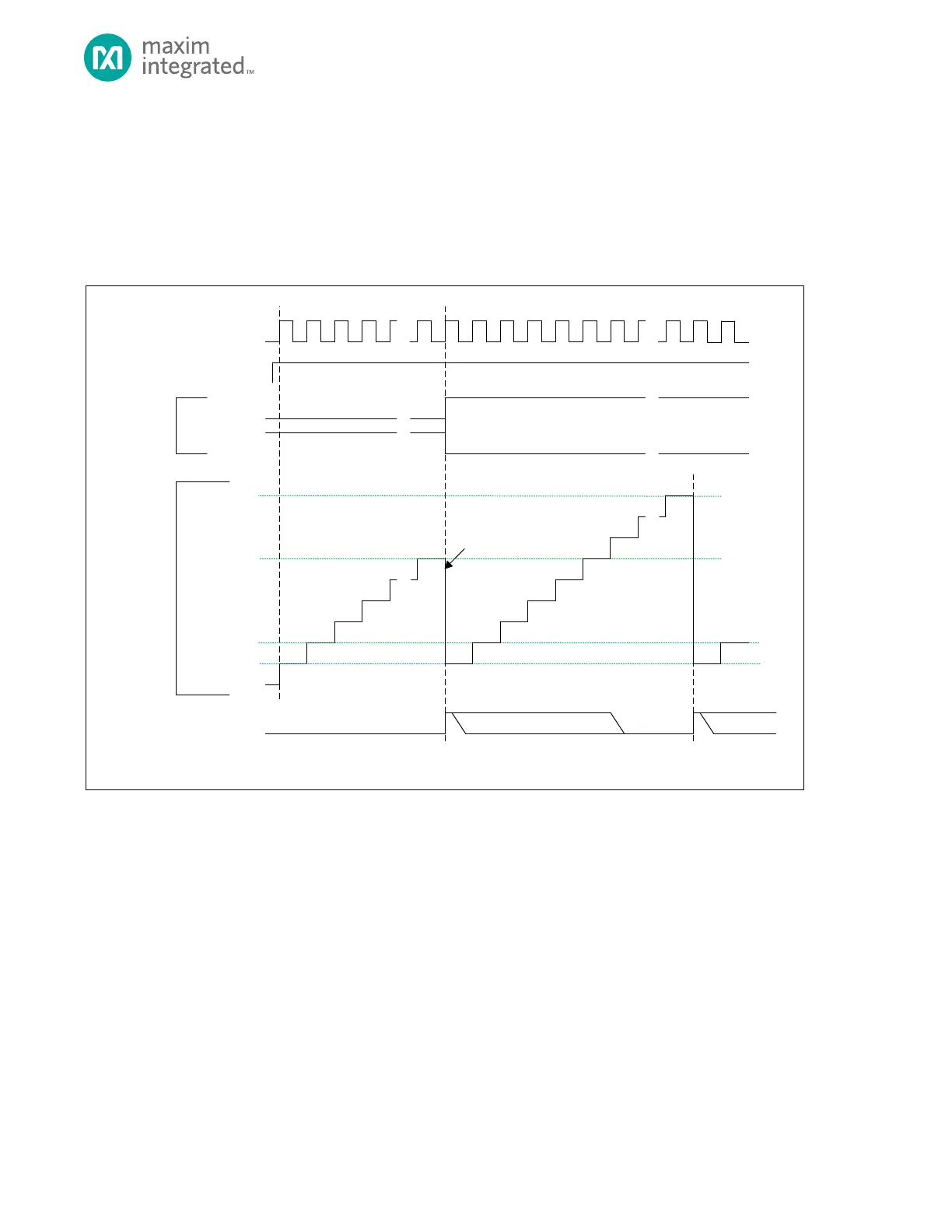
16.8 Capture Mode (100b)
Capture mode most often used to measure the time between events. The timer increments from an initial value until an
edge transition occurs on the timer pin. This triggers the ‘capture’ event which copies TMRn_CNT to the TMRn_PWM.pwm
register, resets TMRn_CNT = 0x0000 0001, and continues incrementing. Also, if the timer pin does not go active before
TMRn_CNT = TMRn_CMP, the timer will reset TMRn_CNT = 0x0000 0001, and continue incrementing. Either event will set
the timer interrupt bit.
Figure 16-4: Capture Mode Diagram
TMR_CN.TEN
TMR_CNT
0X0000_0000**
0X0000_0001*
TMR_INT.IRQ
TIMER CLOCK
TMR_CMP
* TM R_CNT AUTOMATICALLY RELOADS WITH 0X0000_0001 AFTER A CAPTURE EVENT OR WHEN TMR_CNT = TMR_CMP, BUT SOFTWARE CAN WRITE ANY INITIAL
VALUE TO TMR_CNT BEFORE THE TIMER IS ENABLED.
** THE DEFAULT VALUE OF TMR_CNT FOR THE FIRST PERIOD AFTER A SY STEM RE SET IS 0X0000_0000 UNLESS CHANGED BY SOFTWARE.
SOFTWARE CLEARS .IRQ BIT
TIMER PIN
(INPUT)
0X0000_0002
TMR_CNT
(CAPTURE)
TMR_CN.TPL = 1
TMR_CN.TPL = 0
TMR_CNT
(CAPTURE)
COP IED TO TMR_PWM